8. INSTALLATION STEPS
8-1. MEASURE AND MARK DOOR AREA
Horizontal
Reinforcement
Bracket
Header
Horizontal Line for
Header Bracket
Height
Door Width
See Fig. 12
See Fig. 11
Vertical
Center Line
Identify a sound structural support on header wall above garage
door for header bracket mounting. See Fig. 11. If appropriate
header does not exist, replace or install a new support using a 2x4
or 2x6 board. Fasten it securely using lag screws (not provided) to
structural supports of garage.
Before starting your installation, the door and the header above
the door must be measured and marked. This way, the appropri
-
ate brackets can be mounted at the correct locations avoiding
installation and operating difficulties later.
MARK VERTICAL CENTER LINE:
Measure door width, then locate the center point (Fig.10).
Mark a vertical line on the upper half of your door, on the top
edge of your door, and on the header, through the center
point.
MEASURE DOOR’S HIGHEST TRAVEL POINT:
(Review Figs. on p. 5 for details)
Open door to its highest travel point and measure from the
garage floor to the top of door.
Write down this distance.
FOR SECTIONAL DOORS AND ONE-PIECE DOORS WITH
HORIZONTAL TRACK:
Add 1-1/4" to the door travel height (measured above).
FOR ONE-PIECE DOORS WITHOUT TRACK:
Add 3-3/4" to the door travel height (measured above).
MARK HORIZONTAL LINE FOR HEADER BRACKET
LOCATION:
Close door and measure the required distance (determined
above) from the garage floor to the header.
Mark a horizontal line, intersecting the vertical center line, on
header. This is the position at which the bottom of the header
bracket should be installed.
In case of minimal clearance above the door, the header
bracket may be mounted to the ceiling. In this case, extend
the vertical center line onto the ceiling, and mark a horizontal
line on the ceiling no further than 4" from the header wall.
The header bracket should be mounted no farther than this
distance from the header wall.
8
Fig. 10
29
Header
Lag Screw for Header installation
if necessary (not provided)
Header Bracket
5/16 x 1-3/4"
Lag Screw
Pilot Holes
Fig. 11
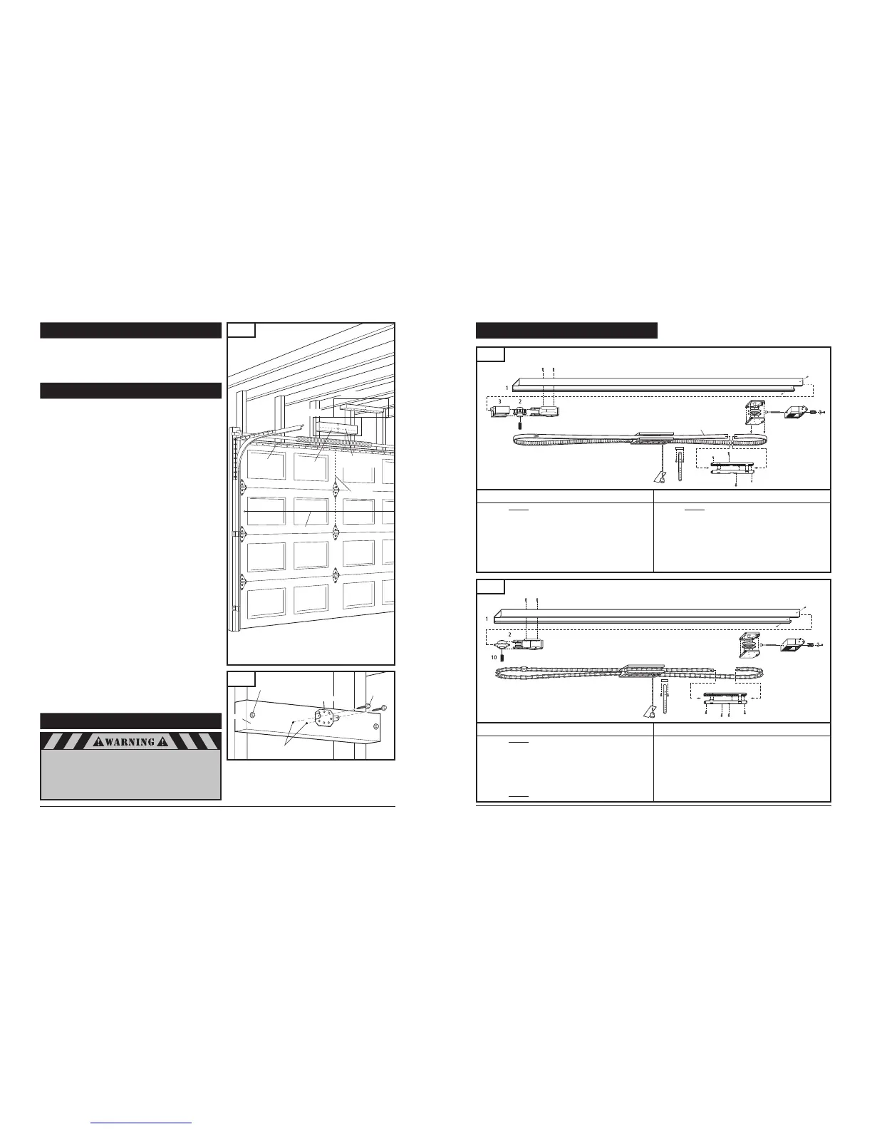
17. RAIL ASSEMBLY PARTS
Fig. 52
Belt Rail Assembly
Model#: ML-807B (7' Door) ML-808B (8' Door) ML-810B (10' Door)
Item Part # Description
1. Rail
2. 8030337 Sprocket holder assembly
3. 8008709 Belt guide
4. 8030432 Roller holder with tension bolt assembly
5. 8008503 Rail end-stop
6. 8030196 Belt connector
Item Part # Description
7. Belt with position tab
8. 8030177 Trolley assembly (7’ Door)
8030178 Trolley assembly (8’ & 10’ Door)
9. 8008708 Pin
10. 8030735 Straight door arm
11. 8007412 Shaft adapter
Fig. 53
Item Part # Description
1. Rail
2. 8030339 Sprocket holder assembly
3. 8030432 Roller holder with tension bolt assembly
4. 8008503 Rail end-stop
5. 8030234 Chain connector
6. Chain with position tab
Item Part # Description
7. 8030177 Trolley assembly (7’ door)
8030178 Trolley assembly (8’ & 10’ Door)
8. 8008708 Pin
9. 8030735 Straight door arm
10. 8007412 Shaft adapter
Chain Rail Assembly
Model#: ML-807C (7' Door) ML-808C (8' Door) ML-810C (10' Door)
Power Head End
Power Head End
8-2. INSTALL HEADER BRACKET
If the header bracket is not rigidly fastened to a sound
structural support on the header wall or ceiling, the
safety reverse system may not work and could cause
serious injury or death. DO NOT move or adjust springs
or garage door hardware, as these parts are under
extreme tension and could cause injury or death.
6
 Loading...