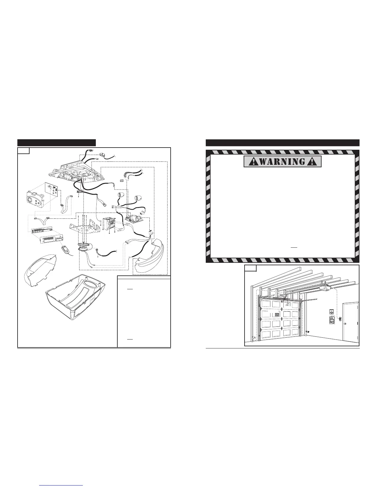
18. OPERATOR ASSEMBLY PARTS
Item Part # Description
1 80349 Lamp Lens
1a 80348 Lamp Lens
2 83890 Housing with Labels
3 Chassis
4 78936 Wire Harness
5 8054389 Reference Switch
6 8030987 Power Cord
7 8007776 Strain Relief Cover
8 73557 Ribon Cable
9 73109 Ribon Cable
10 78914 Logic Board
11 79011 Control Panel
12 78938 Terminal Board
13 70014 Terminal Board Housing
14 78236 Modular Receiver
15 78157 Transformer
16 73699 Wire Harness (Motor / Transformer)
17 72784 Power Board
18 8055529 RPM Sensor w/Wire Harness
19 73894 Motor Assembly
20 Mounting Plate
21 60379 Clip
22* 83388 Harness (Locmatic ready operator)
7. IMPORTANT INSTALLATION INSTRUCTIONS
Shown on the right is an
overall view of a completed
garage door operator system
installed on a sectional door.
The arrangement is similar for
a one-piece door (except for
differences described later in
this manual).
IMPORTANT INSTALLATION INSTRUCTIONS
TO REDUCE THE RISK OF SEVERE INJURY OR DEATH:
1. READ AND FOLLOW ALL INSTALLATION INSTRUCTIONS.
2. Check with the door manufacturer to determine if additional reinforcement is required to support the door prior to
installation of the garage door operator.
3. Install garage door operator only on a properly balanced garage door. An improperly balanced door could cause
serious injury. Have a qualified service person make repairs to garage door cables, spring assemblies, and other
hardware before installing the opener .
4. Remove all ropes and disable all locks connected to the garage door before installing operator.
5. If possible, install the door operator 7 feet or more above the floor. Adjust the emergency release cord so that knob
hangs 6 feet above the floor.
6. Do not connect the operator to source of power until this manual instructs you to do so.
7. Locate the wall control panel: (a) within sight of door, (b) at a minimum height of 5 feet above the ground so small
children cannot reach it, and (c) away from all moving parts of the door.
8. Place the Operating Warning Label next to the wall control panel in a prominent location. Affix Safety Label on
inside of garage door. The Emergency Release Tag must remain on the emergency release cord.
9. After installing the operator, test Safety Reversal System. Door MUST reverse when it contacts a 1-1/2 inch high
object (or a 2x4 laid flat) on the floor.
For Important Safety Instructions see page 25.
730
Fig. 54
M4700e Operator
1
2
22
11
33
44
55
66
77
88
1
2
3
4
5
6
7
8
9
1
0
1
1a
2
3
5
6
7
6
4
8
9
10
11
12
13
15
16
17
18
19
20
14
*Guide for part replacement only
5
18
21
Fig. 9
Operating
Warning
Label
Owner’s
Manual
Garage Door
Safety Label
Emergency
Release Tag
22
22
 Loading...