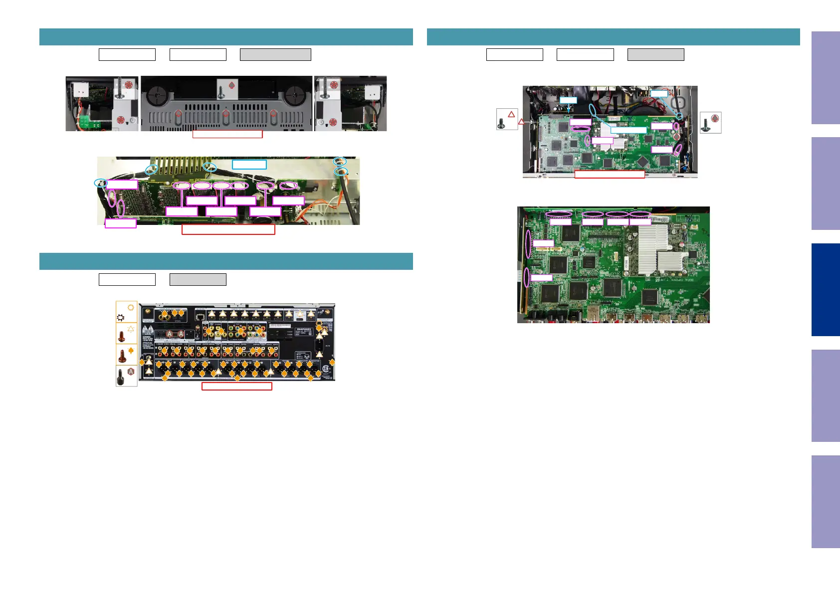
Proceeding : TOP COVER → FRONT ASSY → RADIATOR ASSY
(1) Removethescrews.
(2) Cutthewireclamp,thenremovetheconnector.
Proceeding : TOP COVER → REAR PANEL
(1) Removethescrews.
2. RADIATOR ASSY
View from the bottom
x3
x1 x1
↑Shooting direction: A↑
CN482
CN481
CN483CN923CN921
CN484CN922CN920
CUT x5
3. REAR PANEL
↑Shooting direction: A↑
x2
x49
x17
x2
Proceeding : TOP COVER → REAR PANEL → DIGITAL PCB
(1) Removethescrews.RemovetheRivet.Cutthewireclamp,thenremovetheconnector.
RemovetheFFC.RemovetheSTYLEPIN.
(2) Removetheconnector.
4. DIGITAL PCB
↑Shooting direction: A↑
x1
x1
BN321
CN903
JK433
FFC
Rivet
STYLE PIN
CUT
BN24A BN26A BN25A BN21A
BN23A
BN27A
Before Servicing
This Unit
Electrical Mechanical Repair Information Updating
83


 To Next Page