43
2. DISPLAY CONTROL PWB (PF01) / PHONE PWB (PH01)
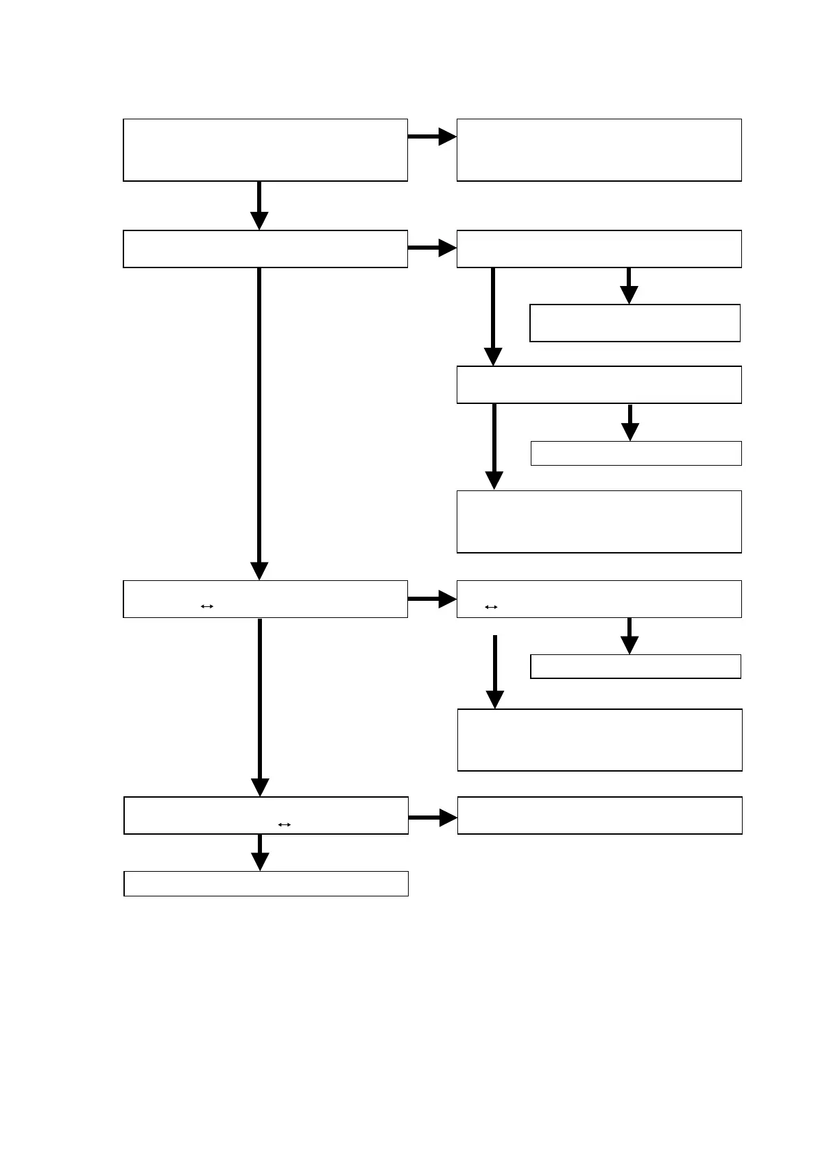
2.1 FL is not outputted.
Is the 61pin of the QF71 line H?
OK
NG
NG OK
NG
OK
OK
OK
OK
NG
NG
NG
NG
OK
Is the connector (JF02) voltage line
normal?
+5V_D1, -27V, DC+3.5V and HEATER
Are the 62,63 and 64 pin of QF71 signal
normal? (H L)
Are the 1 to 40pin and 42 to 54pin of
QF71 signal normal? (H L)
Replace VF01.
Replace QF71.
Check the soldering of RF08, RF09,
RF10, JF01 (8,10,11pin) and QU01
(9,70,73pin).
Replace QF80 or / and QF71.
Check the 2,5 and 12 pin of QF80 signal.
(H L)
Check the soldering of RF11, RF80,
CF11, CF81, JF01 (12pin) and
QU01 (71pin).
Replace QF80.
Check the Signal of QF80 (9pin).
Reset = H
Check the soldering of RF72
and CF74.
Check the 8pin of QF80 Signal.
Reset = H
Check the soldering of these componentson
the POWER SUPPLY PWB (P801) and
DISPLAY CONTROL PWB (PF01).