45
3. Main PWB (PM01)
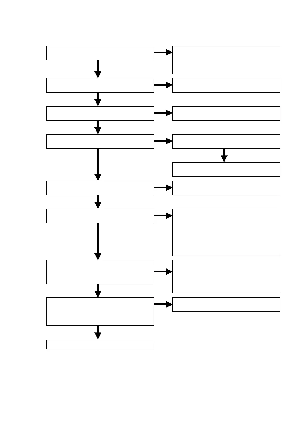
3.1 Check the panel microprocessor
OK
OK
NG
NG
NG
OK
OK
OK
NG
NG
OK
OK
NG
NG
OK
NG
OK
Are the E+6V and E+3.3V of QU91
voltage lines normal?
Is the reset signal of QU01 (59pin) normal?
Is the master clock waveform normal?
12.000MHz
Is not QU01 write-in mode?
67pin=H, 66pin=L
Is each output voltage normal?
(After the 15pin of QU01 changed to H)
Is communication to QT01 and QU01
(78pin and 79pin) normal?
Is communication to Q301 and QU01
(75pin and 79pin) normal?
Is 88pin of QU01 H?
Is communication to Q102 normal?
Is 28pin of QU01 H?
Is communication of 38pin, 83pin, 84pin
and 85pin on QU01 normal?
Finish
• E+6V=0V: Check the E+6V voltage line
on POWER SUPPLAY PWB (P801).
• E+3.3V=0V: Check the soldering of
QU01, or replace QU91.
Check the soldering and the input/output
voltage of QU03.
Check the soldering XU01 and QU01
(63pin and 65pin).
Check the soldering of ST81, CT86 and
QU04.
Replace QU04.
Refer to “1. POWER SUPPLAY PWB (P801)”.
• Check the soldering of QT01,
circumference components and power
supply line.
• Check the soldering QT05, QW81,
QW01, QW02 and QW03.
• Check the output voltage of QT05 and
QW81.
• Check the soldering of Q301, Q302,
RU72, RU73 and RU74.
• Check the power supply line of Q301.
• Check the frequency of 126pin on Q301.
(12.288MHz)
Refer to “3.2 Check the B/E microprocessor”.