56
4. HDMI PWB (PD01)
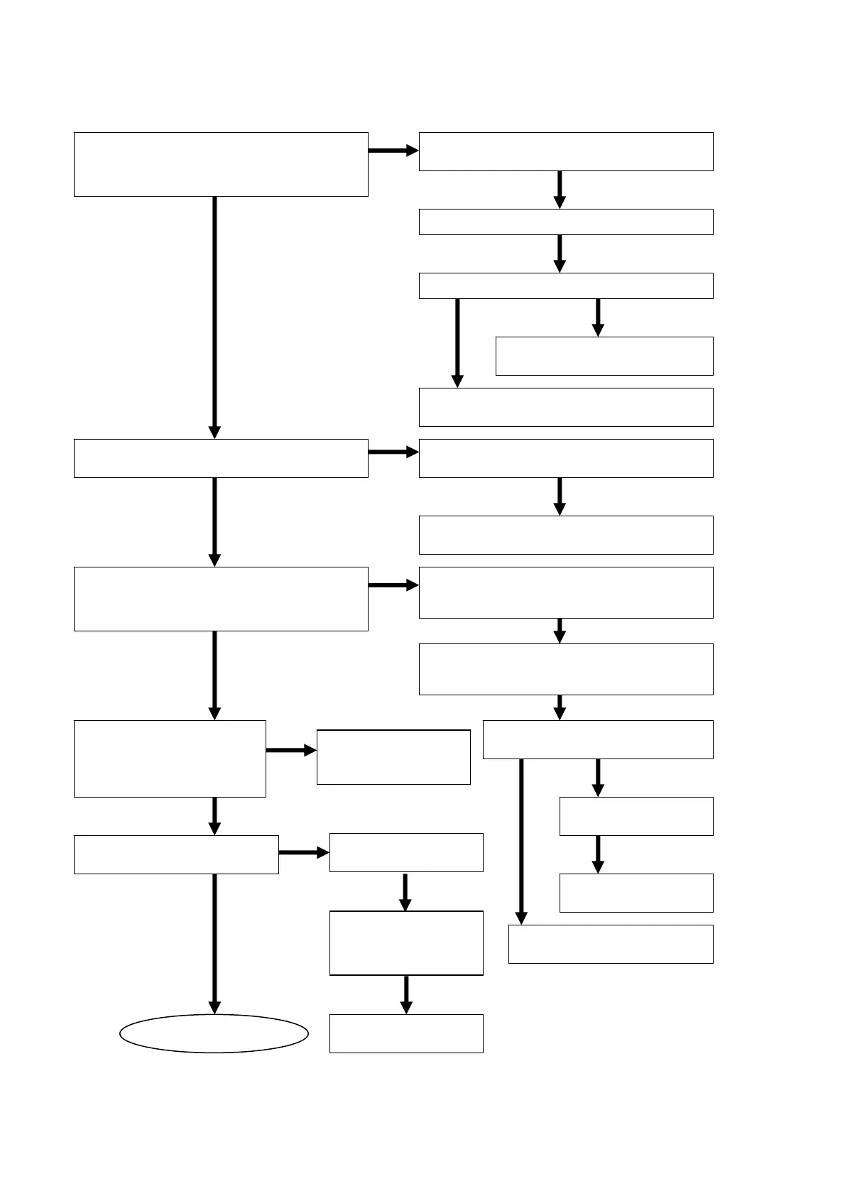
4.1 Check the Scaler.
Check the soldering of LW01-LW03,
QW01 and QW81-QW83.
Are the SC+3.3V_1, SC+2.5V_1 and
SC+1.2V_1 voltage lines of QW01
normal?
Check the input voltage of QW81-QW83.
Check the VD_PSW level. VD_PSW=L
Replace QW81, QW82 or
QW83.
Check the soldering of JQ02, JK02 (8pin)
and QU01 (1pin).
Check the soldering of QW01, RW12.
Is the reset signal of QW01 H?
RW12 VRST_3=H
Check the soldering of JW02, JK02 (2pin)
and QU01 (24pin).
Check the soldering of JW01, JK01,
RW01-RW06, RW09, RW17, RW38 and
W
1.
Are the digital data input signals normal?
PY_2䇼0-9䇽, SDCLK_2, SDHSYNC_2,
SDVSYNC_2, DE.
Check the soldering of QK05-QK06,
QK13 and circumference components of
K14.
Check the input signals of
QK04-QK06.
Check the voltage
line QK04-QK06.
Refer to “3.4 check the
DIGITAL VIDEO OUTPUT”
Replace
QK04-QK06.
Refer to Scaler 2
NG
OK
NG
OK
NG
OK
OK
OK
OKNG
OK
OK
OK
OK
NG
Is the voltage lines of
QW05 normal?
19, 20pin 䋨SC+2.5V_1)
18pin (SC+3.3V_1)
NG
Check the soldering
of QW05, CW48-䌃
䌗50.
Is the signal of QW05 H?
10pin (CONFIGDONE)=H
OK
NG
Check the soldering
of RW18-R䌗21 and
RW23.
Replace QW05.
NG
NG
OK
#HECKTHESOLDERING
OF272䌗
/+