11
Part namesGetting started Connections Operations
ENGLISH
Explanation of terms IndexSpecifi cationsTroubleshooting
Specifi cations
Rated power output
(from 20 Hz to 20 kHz/THD = 0.08 %, two channels driven): 150 W/ch, 8 Ω
180 W/ch, 6 Ω
Maximum effective output power
(from 1 kHz, 6 Ω, 10% two channels driven): 210 W/ch, 6 Ω
Output connectors: 6 – 8 Ω
Frequency response (1 W, 8 Ω): 8 Hz – 100 kHz (±3 dB)
Damping factor: 100
Input sensitivity/impedance: 1.2 V / 22 kΩ (UNBALANCED)
2.4 V / 30 kΩ (BALANCED)
Signal-to-noise ratio (IHF-A): 105 dB
Voltage amplifi cation level: 29 dB
Supply voltage: AC 230 V, 50/60 Hz
Power consumption: 880 W
Standby power: 0.4 W
For purposes of improvement, specifi cations and design are subject to change without notice.
Index
v Numerics
7.1ch surround playback ······································ 5
9.1ch surround playback ······································ 5
11.1ch surround playback ···································· 5
v A
Accessories ·························································· 1
Audio cable ··························································· 4
Auto standby function ·········································· 9
v B
Balanced cable ····················································· 4
v C
Condensation ······················································· 2
Connection
Balanced ···························································· 6
External control device ······································ 8
Power cord ························································ 7
Remote control ·················································· 7
Unbalanced ························································ 6
v E
Example connection variation ······························ 5
v F
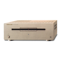
Front panel ··························································· 3
v P
Protection circuit ················································ 10
v R
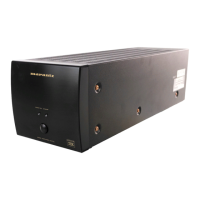
Rear panel ···························································· 3
v S
Sets the connected input connectors ·················· 4
Speaker cable ······················································· 4
Speaker impedance ············································ 10
Switching the illumination lamp ON/OFF ············· 9
v T
Troubleshooting ················································· 10
Turning the Power On ·········································· 9
Turning the power standby ·································· 9
v X
XLR connector PIN arrangement ························· 4
v Z
ZONE2 ·································································· 5
ZONE3 ·································································· 5
1.MM8077NENG2nd1030.inddSec111.MM8077NENG2nd1030.inddSec11 2012/11/0116:56:402012/11/0116:56:40