2-31 2-32
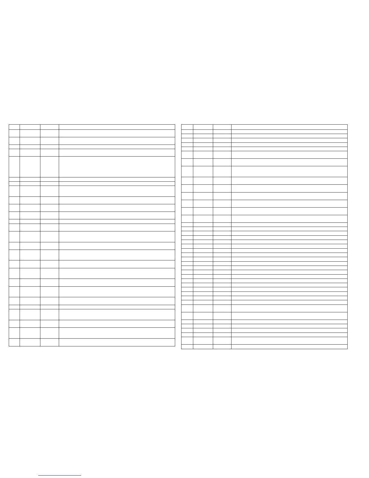
IC805 RH-iX1539GEZZ: Flash ROM (IX1539GE) (1/2)
1-3 A15-A13 Input Block select addresses: Select 1/32 erase block. These addresses are latched during data entry,
erase and lock block.
4-8 A12-A8 Input Word select addresses: Select one word in 1.6k byte block.
These addresses are latched during data entry.
9*, 10* NC - Not used
11 WR Input Write enable: Controls access to command user interface, to data cue register and to address
cue latch. At Low, WR is active to input address and data at leading edge.
12 /RP Input Reset/power-down: By setting /RP at Low, control circuit is initialized when supplying power.
When supplying/breaking power, /RP pin is maintained at Low to protect data.
If /RP is at Low, device is in condition of deep power down.
To return from the deep power down, 480ns is required.
When pin /RP is at Low, all chip operation is interrupted and reset.
After return, device reads array.
13 VPP - Device power supply: 5.0 V
14 /WP - Write/Erase power supply: 5.0±0.5V is applied during the writing/erasing operation.
15 RY/BY Output Ready/Busy: Outputs the condition of the internal write state machine. "Low" shows the write
state machine is in operation. When the machine is waiting for the next instruction to operate,
interrupting erasing, or in deep power-down condition, RY/BY pin is in the float condition.
16,17 A18, A17 Input Block select addresses: Select 1/32 erase block. These addresses are latched during data entry,
erase and lock block.
18-25 A7-A0 Input Word select addresses: Select one word in 1.6k byte block.
These addresses are latched during data entry.
26 /CE Input Chip enable: Makes control logic, input buffer, decoder, and sense amplifier of the device active.
Only when /CE is Low, chip becomes active.
27 GND - Ground
28 /OE Input Output enable: By setting /OE at Low, data are output from pin DQ.
If /OE is set at High, pin DP becomes in the float condition.
29 DQ0 Input/Output Lower byte data input/output: Data and command input during cycle of writing command user
interface. Memory array, identifier, and status data output when reading various data.
Float condition in case of chip non-select or output disable.
30 DQ8 Input/Output Upper byte data input/output: The function is the same as shown in case of the lower byte data
input/output above. Operating only in x16 mode. Floating in x 8 mode. DQ15/A-1: address
31 DQ1 Input/Output Lower byte data input/output: Data and command input during cycle of writing command user
interface. Memory array, identifier, and status data output when reading various data.
Float condition in case of chip non-select or output disable.
32 DQ9 Input/Output Upper byte data input/output: The function is the same as shown in case of the lower byte data
input/output above. Operating only in x16 mode. Floating in x 8 mode. DQ15/A-1: address
33 DQ2 Input/Output Lower byte data input/output: Data and command input during cycle of writing command user
interface. Memory array, identifier, and status data output when reading various data.
Float condition in case of chip non-select or output disable.
34 DQ10 Input/Output Upper byte data input/output: The function is the same as shown in case of the lower byte data
input/output above. Operating only in x16 mode. Floating in x 8 mode. DQ15/A-1: address
35 DQ3 Input/Output Lower byte data input/output: Data and command input during cycle of writing command user
interface. Memory array, identifier, and status data output when reading various data.
Float condition in case of chip non-select or output disable.
36 DQ11 Input/Output Upper byte data input/output: The function is the same as shown in case of the lower byte data
input/output above. Operating only in x16 mode. Floating in x 8 mode. DQ15/A-1: address
37 VCC - Device power supply: 5.0±0.5V
38 DQ4 Input/Output Lower byte data input/output: Data and command input during cycle of writing command user
interface. Memory array, identifier, and status data output when reading various data.
Float condition in case of chip non-select or output disable.
39 DQ12 Input/Output Upper byte data input/output: The function is the same as shown in case of the lower byte data
input/output above. Operating only in x16 mode. Floating in x 8 mode. DQ15/A-1: address
40 DQ5 Input/Output Lower byte data input/output: Data and command input during cycle of writing command user
interface. Memory array, identifier, and status data output when reading various data.
Float condition in case of chip non-select or output disable.
41 DQ13 Input/Output Upper byte data input/output: The function is the same as shown in case of the lower byte data
input/output above. Operating only in x16 mode. Floating in x 8 mode. DQ15/A-1: address
Pin No.
Terminal Name Input/Output
Function
In this unit, the terminal with asterisk mark (*) is (open) terminal which is not connected to the outside.
IC901 VHiCXD2751Q-1: SACD Playback Signal Processor (CXD2751Q) (1/2)
1 XSRQ Output Output terminal for data request to be input in the front end processor.
2 XSHD Input Input terminal for header flag to be output from the front end processor.
3 VDD - Power supply terminal, +3.3V
4 VSS - Ground terminal
5 SDCK Input Input terminal for data transmitting clock to be output from the front end processor
6 SMUTE Input Soft mute terminal
H: Soft mute of audio output, L: Released
7 XMSLAT Input Latch input terminal for microcomputer serial communication
Latches addresses and data when this terminal rises.
8 MSCK Input Shift clock input terminal for microcomputer serial communication
Inputs and shifts the serial input data when the clock to be input in this terminal rises.
Read-out data change when the clock to be input in this terminal falls.
9 MSDATI Input Data input terminal for microcomputer serial communication (Microcomputer -> CXD2751Q)
Inputs serial data and addresses for communication.
10 MSDATO Output Data input terminal for microcomputer serial communication (CXD2751Q -> Microcomputer)
High impedance except during output
11 MSREDY Output Ready-to-output flag for microcomputer serial communication. Outputs "L", if complete.
Open drain.
12* XMSDOE Output Data enable terminal for microcomputer serial communication
Makes this terminal active when using the try state buffer outside.
13 XRST Input Resets entire IC when reset terminal is "L".
Clock which is output from output terminals EXCKO1, EXCKO2, and LRCK does not stop during reset.
14 MCKI Input Master clock input terminal
Inputs clock of 512Fs (22.579 MHz) or 768Fs (33.869 MHz).
15 VSS - Ground terminal
16 CK75S Input Master clock select terminal. Selects "H" in case of 768Fs and "L" in case of 512Fs.
17 EXCKO1 Output External output clock terminal 1. Outputs 768Fs/512Fs/256Fs/128Fs according to setting.
18* EXCKO2 Output External output clock terminal 2. Outputs 768Fs/512Fs/256Fs/128Fs according to setting.
19* LRCK Input/Output IFs (44.1kHz) clock input/output terminal. Selects master/slave according to setting.
20* NC - Not used
21* MNT2 Output Monitor output terminal. Outputs partial internal operation according to setting.
22 TRST Input Reset terminal for test. Inputs power-on reset signal or fixed at "L".
23 TCK Input Test clock input terminal. Fixed at "L".
24* TDI Input Test input terminal. Open
25* TENA1 Input Test input terminal. Open
26* TDO Output Test input terminal. Open
27 VST - Test ground terminal. Connected to ground
28 VDD - Power supply terminal, +3.3V
29 VSS - Ground terminal
30*, 31* MNT1, MNT0 Output Monitor output terminal. Outputs partial internal operation according to setting.
32* XBIT Output DST related monitor terminal. Not connected.
33* F75HZ Output 75Hz clock output terminal
34* SUPDAT Output Supplementary data serial output terminal
35* XSUPAK Output Supplementary data effective flag terminal
Outputs "L" when supplementary data are effective.
36* SUPEN Output Supplementary data byte-unit enable output terminal
Changes to "H" at the break of 1 byte (8 bits) of serial data.
37 TEST1 Input Test input terminal. Fixed at "L".
38 VSS - Ground terminal
39 TEST2 Input Test input terminal. Fixed at "L".
40, 41 VSS - Ground terminal
42* BCKD Input/Output Phase reference signal input/output terminal for DSD data phase modulation output
Input/output according to setting
43*-45* NC - Not used
Pin No.
Terminal Name
Input/Output
Function
In this unit, the terminal with asterisk mark (*) is (open) terminal which is not connected to the outside.
 Loading...