EasyManua.ls Logo

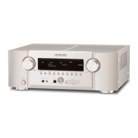
Marantz SR5003 Service Manual

Marantz SR5003
176 pages
To Next Page IconTo Next Page
Page #1 background imageLoading...
Page #1 background image
SR6003
Please use this service manual with referring to the user guide ( D.F.U. ) without fail.
Service
Manual
SR6003
SR6003 /
F B/N1B/U1B
/K1SG/N1SG
Part no. 90M08DW855010
First Issue 2008.08
MZ
AV Surround Receiver
TABLE OF CONTENTS
SECTION PAGE
1. TECHNICAL SPECIFICATIONS ........................................................................................... 1
2. TECHNICAL DESCRIPTION ................................................................................................ 6
3. POWER AMPLIFIER ADJUSTMENT.................................................................................... 8
4. SERVICE MODE ................................................................................................................... 9
5. SYSTEM ERROR ............................................................................................................... 11
6. DUAL BACKUP MEMORY .................................................................................................. 15
7. UPDATE FIRMWARE .......................................................................................................... 16
Mode 1 : Update/Download MAIN CPU's software to internal Flash-ROM .................... 17
Mode 2 : Update/Download DSP's software to Flash-ROM ........................................... 23
Mode 3 : Update/Download HDMI CPU's software to internal Flash-ROM ................... 29
Mode 4 : Update/Download USB CPU's software to internal Flash-ROM ..................... 36
8. WIRING DIAGRAM ............................................................................................................. 43
9. BLOCK DIAGRAM .............................................................................................................. 45
10. SCHEMATIC DIAGRAM ...................................................................................................... 49
11. PARTS LOCATION .............................................................................................................. 79
12. EXPLODED VIEW AND PARTS LIST ............................................................................... 101
13. MICROPROCESSOR AND IC DATA ................................................................................. 106
14. ELECTRICAL PARTS LIST ............................................................................................... 140
15. ABOUT REPLACE THE MICROPROCESSOR WITH A NEW ONE .............................204

Other manuals for Marantz SR5003

Question and Answer IconNeed help?

Do you have a question about the Marantz SR5003 and is the answer not in the manual?

Marantz SR5003 Specifications

General IconGeneral
Channels7.1
HDMI Inputs3
HDMI Outputs1
Component Video Inputs3
Component Video Outputs1
Digital Audio Inputs2 Optical, 2 Coaxial
Analog Audio Inputs6
Response Bandwidth10 Hz - 100 kHz
Signal-To-Noise Ratio105 dB
Total Harmonic Distortion0.08%
Input Sensitivity200 mV
Tuner BandsAM/FM
Dolby DecodingDolby Digital Plus, Dolby TrueHD
DTS DecodingDTS-HD Master Audio
Input Impedance47 kOhm
Video ConversionAnalog to HDMI
Audio DecodersDolby TrueHD, DTS-HD Master Audio
Power Output90 W per channel (8 ohms, 20 Hz - 20 kHz, 0.08% THD)

Summary

Service Manual

1. TECHNICAL SPECIFICATIONS

2. TECHNICAL DESCRIPTION

3. POWER AMPLIFIER ADJUSTMENT

Idling Current Alignment

Procedure for adjusting idling current in the power amplifier.

4. SERVICE MODE

5. SYSTEM ERROR

System Error Checks

Details common system errors, checks, and recovery procedures.

6. DUAL BACKUP MEMORY

How to Operate Dual Backup Memory

Instructions for backing up and recovering settings using the dual backup memory function.

Service Precautions for Dual Backup Memory

Clearing the dual backup memory after replacing Flash ROM or rewriting DSP code.

7. WRITING AND UPDATE SOFTWARE

Update/Download MAIN CPU Software

Procedure to update the software for the MAIN CPU to its internal Flash-ROM.

Update/Download DSP Software

Procedure to update the software for the DSP to its Flash ROM.

Update/Download HDMI CPU Software

Procedure to update the software for the HDMI CPU to its internal Flash-ROM.

Update/Download USB CPU Software

Procedure to update the software for the USB CPU to its internal Flash-ROM.

8. WIRING DIAGRAM

9. BLOCK DIAGRAM

10. SCHEMATIC DIAGRAM

11. PARTS LOCATION

Video A PCB Parts Location

Shows the location of components on the Video A PCB.

Video B PCB Parts Location

Shows the location of components on the Video B PCB.

XM A PCB Parts Location (/U Only)

Shows the location of components on the XM A PCB for /U version.

XM B PCB Parts Location (/U Only)

Shows the location of components on the XM B PCB for /U version.

12. EXPLODED VIEW AND PARTS LIST

13. MICROPROCESSOR AND IC DATA

IC01: R5F2122AASNFP (SR6003: USB)

Pin configuration and description for IC01 (Microprocessor).

IC11: M3087BFLK/M3087BFL (SR5003/SR6003: MAIN)

Pin configuration and description for IC11 (Microprocessor).

14. ELECTRICAL PARTS LIST

Resistors

Lists various resistors with their part numbers, descriptions, and examples.

Capacitors

Lists various capacitors with their part numbers, descriptions, and examples.

Electrolytic Capacitors

Lists electrolytic capacitors with their part numbers, examples, and working voltages.

Film Capacitors

Lists film capacitors with their part numbers and examples.

15. ABOUT REPLACE THE MICROPROCESSOR WITH A NEW ONE

Post-Replacement Procedures

Explains actions for Mask ROM, Flash ROM, and empty Flash ROM replacements.

Related product manuals