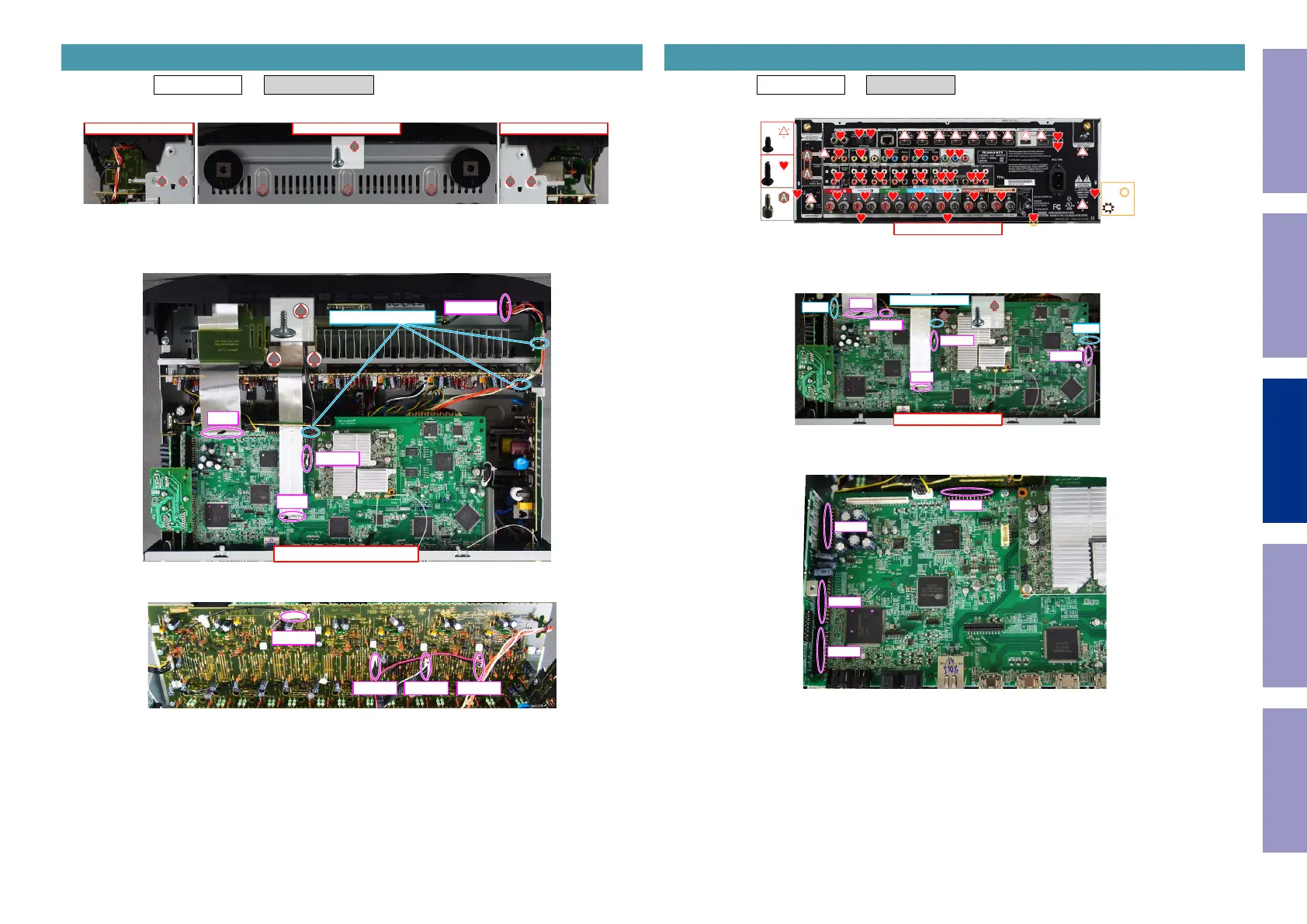
Proceeding : TOP COVER → RADIATOR ASSY
(1) Remove the screws.
(2) Remove the screws. Remove the CORD HOLDER and connectors.
Remove the FFC.
(3) Remove the connector.
2. RADIATOR ASSY
View from the bottom
↓Shooting direction: C↓
↓Shooting direction: D↓
x7
↑Shooting direction: A↑
x2
N1008
CORD HOLDER
CP4400
FFC
FFC
CP402 CP403 CP405
CP401
Proceeding : TOP COVER → DIGITAL PCB
(1) Remove the screws.
(2) Remove the screws. Cut the wire clamp, then remove the CORD HOLDER and connector.
Remove the FFC.
(3) Remove the connector.
3. DIGITAL PCB
↑Shooting direction: A↑
x32
x1
x13
x2
↑Shooting direction: A↑
x1
N1008
CORD HOLDER
FFC
FFC
N1033
N1019
CUT
CUT
N1014
N1016
N1020
N1039
Before Servicing
This Unit
Electrical Mechanical Repair Information Updating
74