b
These instructions refer to the VIDEO PCB unless otherwise specied.
b
These instructions refer to the VIDEO PCB unless otherwise specied.
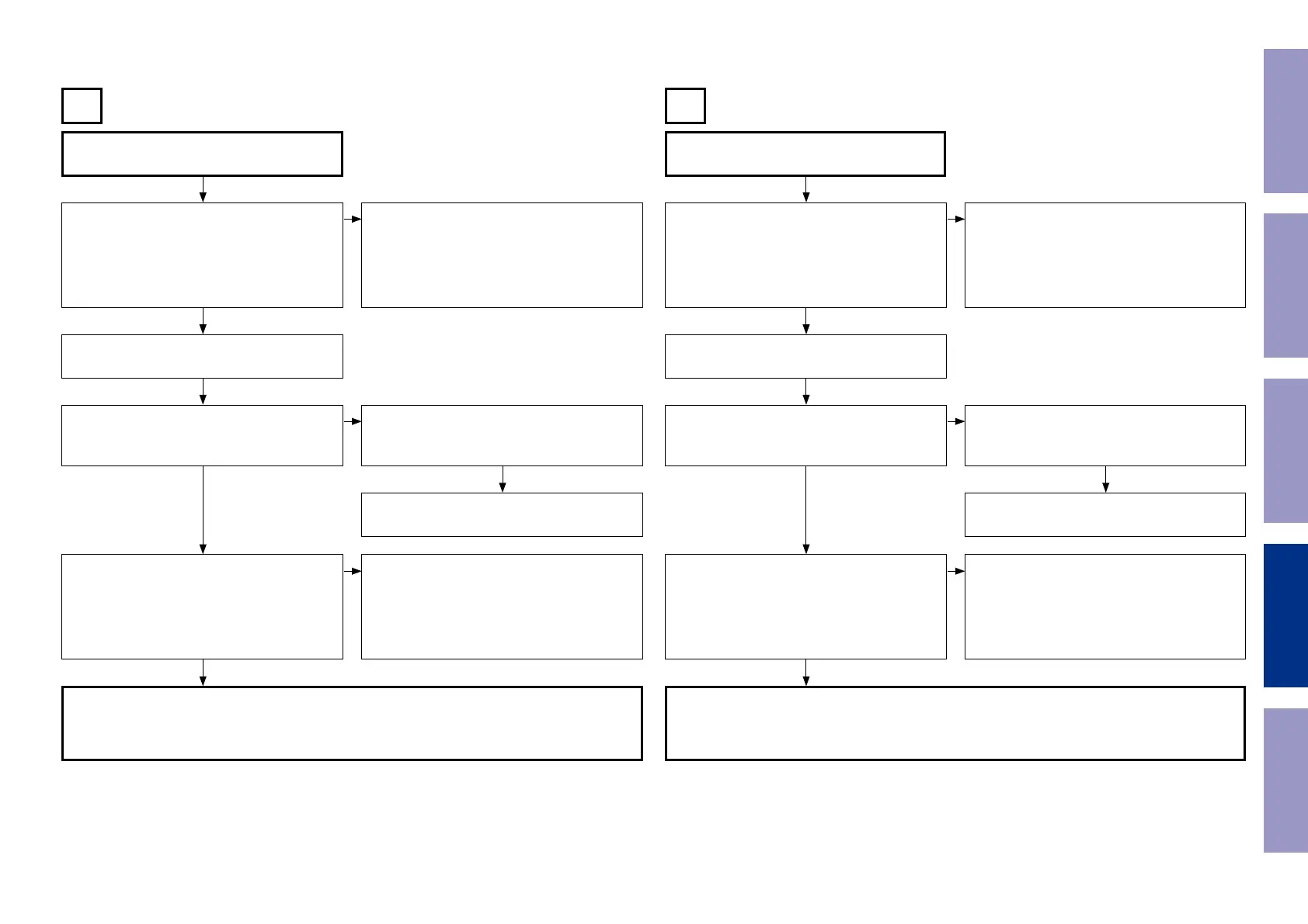
Input
CVBS
Input
COMPONENT
B C
Check the settings of each IC.
Are the following voltages set?
DIGITAL PCB
[N1039 : 12pin] : Hi (3.3 V)
[N1039 : 13pin] : Hi (3.3 V)
[N1039 : 14pin] : Lo (0 V)
Check the settings of each IC.
Are the following voltages set?
DIGITAL PCB
[N1039 : 11pin] : Lo (0 V)
[N1039 : 15pin] : Hi (3.3 V)
Extend the DIGITAL PCB using the jig. Extend the DIGITAL PCB using the jig.
Is the power voltage being output correctly?
V+5V : [C5029 : + side]
V-5V : [C5031 : - side]
Is the power voltage being output correctly?
V+5V : [C5029 : + side]
V-5V : [C5031 : - side]
Check the connection between the FRONT CON-
NECTOR PCB and the VIDEO PCB.
Check the connection between the FRONT CON-
NECTOR PCB and the VIDEO PCB.
The regulator part of REG PCB is faulty. The regulator part of REG PCB is faulty.
Is a signal being output from the video amplier?
CVBS : [JACK5000 : C-OUT]
Is a signal being output from the video amplier?
COMP-Y : [J5032]
COMP-CB : [J5033]
COMP-CR : [J5000]
• Check the [IC5001] power voltage and check
the soldering of the surrounding circuits.
• The pattern between [IC5001 and JACK5000] is
faulty.
• Check the [IC5002] power voltage and check
the soldering of the surrounding circuits.
• The pattern between [IC5002, JACK5002 and
JACK5003] and is faulty.
DIGITAL PCB faulty. DIGITAL PCB faulty.
• Check the connection between the FRONT CONNECTOR PCB and the VIDEO PCB.
• Check the soldering of [CP3401 and CP5000] on the FRONT CONNECTOR PCB.
• Check the soldering of [CN5000] on the VIDEO PCB.
• Check the soldering of [JACK5000] on the VIDEO PCB.
• Check the connection between the FRONT CONNECTOR PCB and the VIDEO PCB.
• Check the soldering of [CP3401 and CP5000] on the FRONT CONNECTOR PCB.
• Check the soldering of [CN5000] on the VIDEO PCB.
• Check the soldering of [JACK5001] on the VIDEO PCB.
q q
w w
e e
r r
NO NO
NO NO
NO NO
YES
YES
YES
YES
YES
YES
NO NO
Before Servicing
This Unit
Electrical Mechanical Repair Information Updating
81