77
19 HPFE I High Pass Filter Enable Pin
"L": Disable
"H": Enable
20 TEST I Test Pin ( pull-down pin)
Should be connected to GND.
21 BGND - Substrate Ground Pin, 0V
22 AGND - Analog Ground Pin, 0V
23 VA - Analog Supply Pin, 5V
24 AINR- I Rch Analog negative input Pin
25 AINR+ I Rch Analog positive input Pin
26 VCOMR O Rch Common Voltage Pin, 2.75V
27 GNDR - Rch Reference Ground Pin, 0V
28 VREFR O Rch Reference Voltage Pin, 3.75V
Normally connected to GNDR with a 10µF electrolytic capacitor
and a 0.1µF ceramic capacitor
Note: All digital inputs should not be left floating
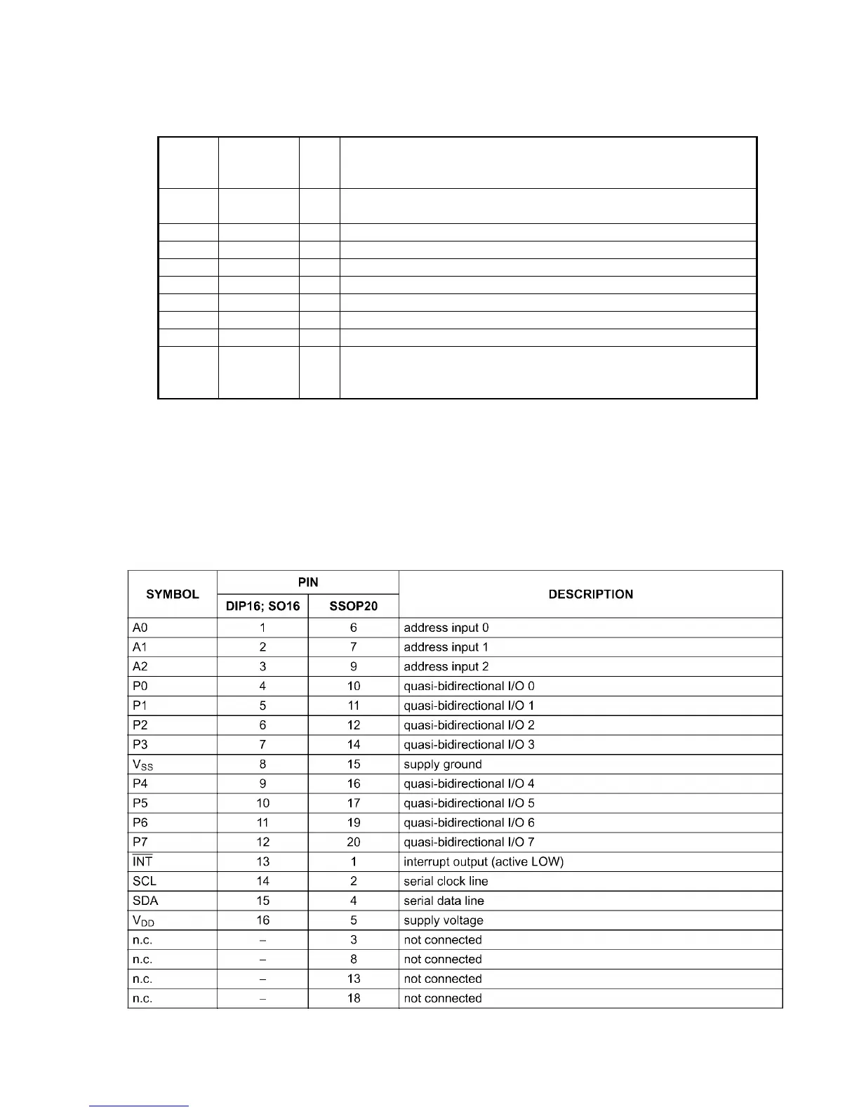
QA07/QU71:PCF8574
Pin Description