99
enter
10. POWER AMPLIFIER ADJUSTMENT
Idling Current Alignment
1. Each of the cement resistors (R132, R182… R432) are provided with the three test points. Set a digital Voltage meter to DC
voltage input, connect the meter to the test points at both ends among the three test points on the cement resistors.
2. After the setup above, turn on the main switch and heat up the amplifier about 10 minutes.
3. Adjust variable resistors (R123, R173… R423) according to the digital voltmeter readings. The target setting value is 2.15 mV
±0.05 mV (10.8 mA) for each channels.
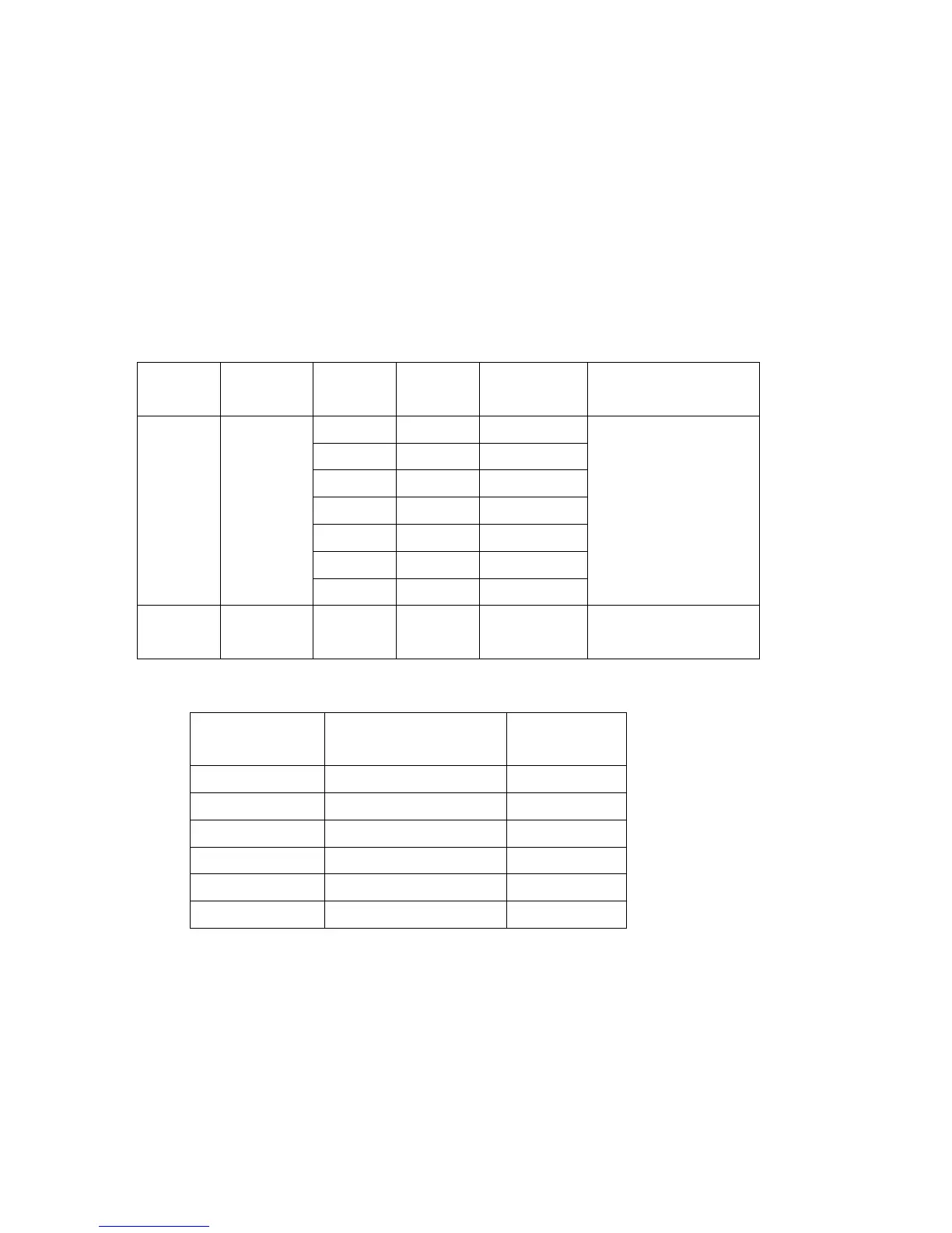
Settings: Master Volume --- Minimum
Speaker out --- No Load
Step Power Channel
Alignment
Point
Measurement
Point
Alignment Value
Front L R123 R132
C R173 R182
Front R R223 R232
Surr. L R273 R282
Surr. R R373 R382
SB L R323 R332
1
Power ON
after
SB R R423 R432
--------------
2
After XX
minutes
R***:0.1ohms
x 2
See table for
alignment value
Time Table of Idling Current Rise
After Turning ON
Measurement Voltage
(R***)
Idling Current
10 min. 2.15 mV 10.8 mA
15 min. 2.13 mV 10.7 mA
20 min. 2.07 mV 10.4 mA
25 min. 2.03 mV 10.2 mA
30 min. 2.00 mV 10.0 mA
40 min. 2.00 mV 10.0 mA
* The Time-Current values in the chart above are from measurement with a unit whose idling current has already adjusted to
10.0mA.
AVSS Function Check
AVSS is the function that switches B voltage automatically depending on the volume of the input signal.
To check whether B voltage is switched or not, follow the procedure below.