24
UD9004
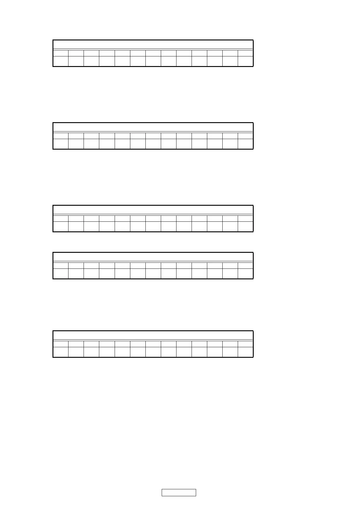
(5) Track buffer output mode
Press the 8 or 9 button to select "Y" and switch the track buffer output.
(Y=1 : Track buffer being output, 0 : Track buffer output off )
When the
2
button is pressed, the layer above the current layer is displayed. See "5.4 Stopping the mode" (page 23).
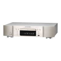
(6) Picking up No. display mode
Press the 8 or 9 button to switch to the pickup number display.
The pickup number is a 14-digit number, so it is displayed in two sections.
(X (display position) = 1 : Lower digits, 2 : Upper digits. YYYYYYY: Pickup number)
When the
2
button is pressed, the layer above the current layer is displayed. See "5.4 Stopping the mode" (page 23).
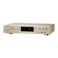
(7) Error log display mode
Press the 8 or 9 button to switch to the error log display.
For Error log No. and description of the displayed measurement results, see "Table 3: Error log details" (page 25).
(n : Error information No.(1 〜 5), X : Error log No.)
Display when there is no error
Press the 8 or 9 button to switch to the [n]. When there is error, error log No. display.
When the
2
button is pressed, the layer above the current layer is displayed. See "5.4 Stopping the mode" (page 23).
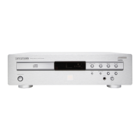
(8) Test mode cancel
A confirmation message is displayed. Press the PLAY button to set, canceling the test mode.
When the
2
button is pressed, the layer above the current layer is displayed. See "5.4 Stopping the mode" (page 23).
FL Display (The display part of 13 digits)
12345678910111213
TEYTrack Buff
FL Display (The display part of 13 digits)
12345678910111213
TGX YYYYYYY
FL Display (The display part of 13 digits)
12345678910111213
nTHX
FL Display (The display part of 13 digits)
12345678910111213
nTH1 No Error
FL Display (The display part of 13 digits)
12345678910111213
TI1 Really?