90-824052R3 JUNE 2002 ELECTRICAL - 2D-27
Engine Synchronizer Wiring Diagram
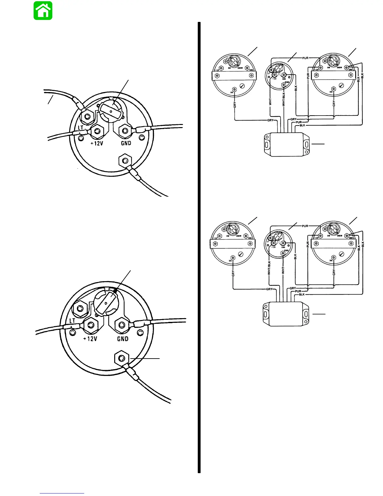
LIGHT BULB POSITION A
Use this position when using a separate light switch
for instrument lighting.
SEND
a
b
51105
a - +12 Volt Light Switch Wire
b - Position Light Bulb to the Unswitched Position
LIGHT BULB POSITION B
Use this position when instrument lighting is wired
directly to the ignition key switch. (Instrument lights
are on when ignition key switch is turned on.)
a
b
51106
a - Position Light Bulb to the Switched Position
b - Sender
Synchronizer wiring can be accomplished two
different ways as an option to the user.
Wiring Diagram – Gauge needle to point toward
slow running engine
GRY=GRAY
WHT=WHITE
BLK=BLACK
PUR=PURPLE
51107
a
b
c
d
a - Tachometer Starboard Engine
b - Synchronizer Gauge
c - Tachometer Port Engine
d - Synchronizer Module
Wiring Diagram – Gauge needle to point toward
fast running engine
GRY=GRAY
WHT=WHITE
BLK=BLACK
PUR=PURPLE
a
b
c
d
51107
a - Tachometer Starboard Engine
b - Synchronizer Gauge
c - Tachometer Port Engine
d - Synchronizer Module
Maintenance
Clean gauge by washing with fresh water to remove
sand and salt deposits. Wipe off with a soft cloth
moistened with water. The gauge may be scored or
damaged if wiped with abrasive material (sand,
saline or detergent compounds, etc.) or washed with
solvents such as trichloroethylene, turpentine, etc.
 Loading...