7-28 - ATTACHMENTS/CONTROL LINKAGE 90-824052R3 JUNE 2002
Transom Mounted
RideGuide Attaching Kit
Installation (73770A1)
Attaching Kit Installation
1. Lubricate both holes in pivot block (Figure 1) with
Quicksilver 2-4-C w/Teflon.
2. Place pivot block on pivot spacer and secure to
transom bracket with 3/8 in. x 2-1/2 in. (9.5mm x
63.5mm) bolt, flat washer and locknut, as shown
in Figure 1. Torque locknut to 20 Ib. ft. (27.0 N·m).
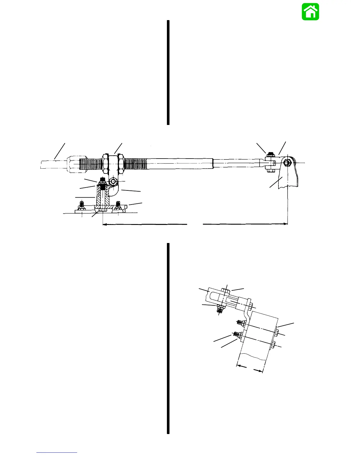
Figure 1
a
b
f
k
d
j
l
c
g
e
i
h
a - RideGuide Cable
b - RideGuide Yoke
c - Pivot Block
d - Pivot Spacer
e - 15 in. (381mm) (Centerline of Attaching Kit Pivot to
Centerline of Outboard)
f - Pivot Attaching Locknut [Torque to 20 lb. ft. (27.0 N·m)]
g - Outboard Steering Arm
h - “Clevis Kit”
i - RideGuide Cable Attaching Locknut [Torque to 10 lb. ft.
(13.6 N·m)]
j - Bolt [3/8 in. x 2-1/2 in. (9.5mm x 63.5mm)]
k - Flat Washer
l - Transom Bracket
3. Place RideGuide yoke on pivot block and secure
with 7/16 in. x 1-3/4 in. (11.1mm x 44.5mm) bolt
and locknut, as shown in Figures 1 and 2. Torque
locknut to 10 Ib. ft. (13.5 N·m), then back off
1/4-turn.
Figure 2
f
g
d
b
c
e
a
a - Transom Backing Plate
b - Bolt [5/16 in. x 3-1/4 in. (7.9mm x 82.5)]
c - Locknut [Torque to 10 lb. ft. (13.5 N·m)]
d - RideGuide Yoke Attaching Locknut [Torque to 10 lb. ft.
(13.5 N·m)] Then Back Off 1/4-Turn
e - 2-3/8 in. (60.3mm) Maximum Transom Thickness
f - Bolt [7/16 in. x 1-3/4 in. (11.1mm x 44.5mm)]
g - RideGuide Yoke
 Loading...