90-824052R3 JUNE 2002 LOWER UNIT - 6E-37
Propeller Shaft/Forward Gear
Bearing Adapter/Bearing Carrier
REASSEMBLY
1. Position sliding clutch onto propeller shaft.
“GROOVED RINGS” are for manufacturing
purposes only and may be positioned towards
either gear. Cross pin hole and detent hole in
sliding clutch must line up with cross pin slot and
detent notch in propeller shaft.
d
a
ge
c
b
51913
f
a - Sliding Clutch
b - Propeller Shaft
c - Grooved Rings
d - Cross Pin Hole
e - Detent Hole
f - Cross Pin Slot
g - Detent Notches
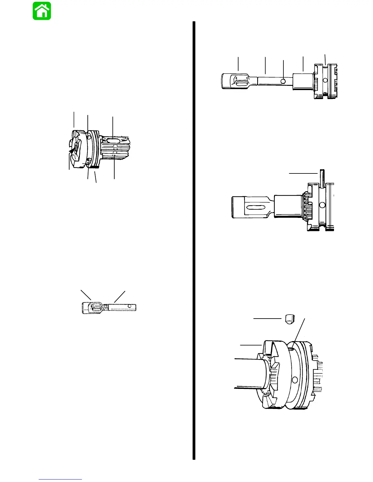
2. Place a small amount of Quicksilver 2-4-C
w/Teflon Lubricant on actuator rod and install
cam follower.
b
a
a - Actuator Rod
b - Cam Follower
3. Slide clutch actuator assembly into propeller
shaft. Align cross pin slot in actuator rod with
cross pin slot in clutch/propeller shaft.
a
b
d
c
e
51875
a - Cam Follower
b - Clutch Actuator Rod
c - Propeller Shaft
d - Cross Pin Slot
e - Clutch/Propeller Shaft
4. Insert cross pin through sliding clutch, propeller
shaft and actuator rod forcing cross pin tool out.
51875
a
a - Cross Pin
5. Apply a small amount of 2-4-C w/Teflon Marine
Lubricant (92-90018A12) to the rounded end of
detent pin. Position detent pin in detent pin hole
of sliding clutch with rounded end of pin toward
propeller shaft.
a
c
b
51879
a - Detent Pin
b - Detent Pin Hole
c - Sliding Clutch
 Loading...