Technical Notice CSO/CPO V1.1 / 10.14 Page 13 / 86
Generalities 2
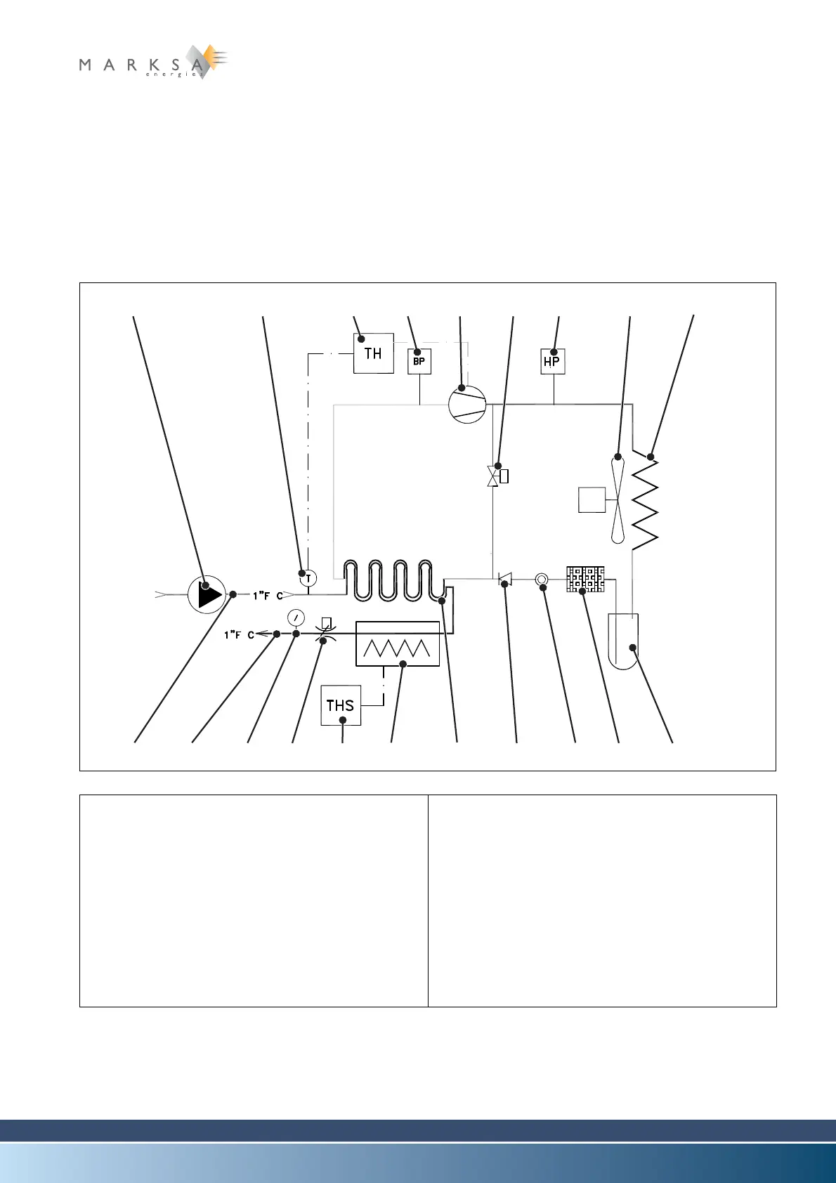
2.3 CSO/CPO principles of operation
The range of CSO/CPO chillers supplies chilled oil (10) continuously at a constant temperature. The
chilling is accomplished in the following manner: An HFC refrigerant of either R134A (tetrafluoroethane)
or R407C types is compressed (5) and then chilled in an air condenser (8). A pressure regulator (16)
causes a drop in pressure which leads to a drop in temperature. The drop in temperature is transmitted
to the oil contained in the unit through an evaporator (15).
The cold oil leaves the unit (10) to chill the end use equipment and then returns back to the unit.
2.3.1 Basic schematic
Fig. 2-1 : Basic schematic
(1) Customer pump (option C - only CPO)
(2) Temperature probe
(3) Thermostat
(4) Safety pressure controllers (LP/HP)
(5) Compressor
(6) Hot gas bypass (option G)
(7) Exhaust fan
(8) Air condenser
(9) Temperate liquid inlet
(10) Cold liquid outlet
(11) Pressure gauge (option V)
(12) Flow rate controller (option F)
(13) Safety thermostat (option H)
(14) Heater (option H)
(15) Evaporator (cleanable exchanger option B -
only CPO)
(16) Pressure regulator
(17) Liquid indicator
(18) Dehumidifier
(19) Liquid reservoir
(1) (2) (3) (5) (4) (7) (8)
(16)
(17)
(19)(13)(12)
(10)(9)
(4)
(14)
(15)
(18)
(6)
(11)