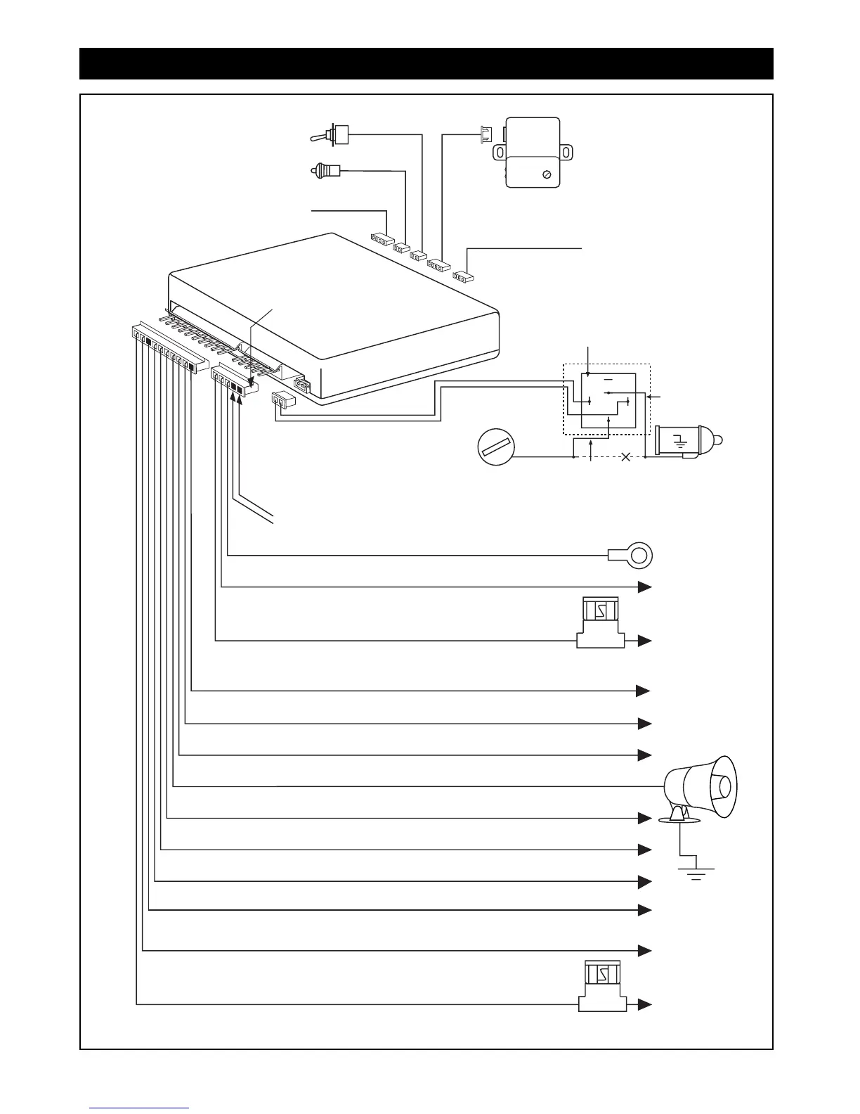
Red Wire with White Stripe
Parking Lights Relay Output (Selectable + or -)
Violet Wire Positive Door Pin Trigger Input
Green Wire Negative Door Pin Trigger Input
Blue Wire Negative AUX Trigger Input
Brown Wire Siren Output (+)
Blue Wire with White Stripe (Channel #3)
Gray Wire Pulsed Ground for Car Horn (Ground)
Vacant Socket
(For Optional Use with ALA-RPT Relay Pack Only, see page 11)
Black Wire Ground to Vehicle Frame
Power Harness
Dome Light Supervision (See Optional Accessory Connection)
Yellow Wire to Ignition Switched +12V
Red Wire to Battery +12V
Pink Wire Parking Lights Relay Input
87
87a
86
85
30
"ACC"
"OFF"
"START"
"ON"
Cut
Starter
Relay Pack
Supplied
Red Wire
Orange Wire
Yellow Wire
White Wire
Vacant Socket (Optional Channel #2
, see page 11)
Shock Sensor
(White Port)
Door Lock Output
(Black Port)
LED Port (White Port)
Valet (Blue Port)
External 2-Way Antenna
Requires M5A2WP (Black Port)
M5a Wiring Diagram
M5A-IM 2-10-04 Rev. B
© Copyright 2004 Magnadyne Corporation
M5A-IM 9/10/04 9:27 AM Page 20