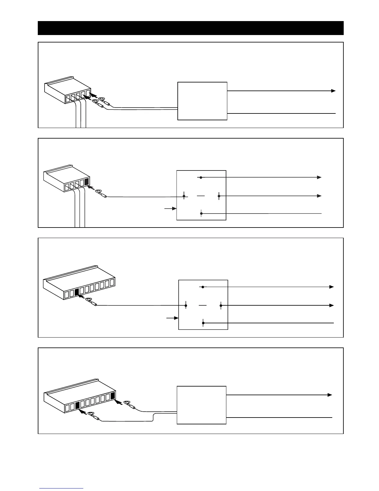
Red Wire
ALA-RPT
Relay Pack
Orange Wire
Output to Trunk Switch
Purple Wire
Input to Relay (+ or
-
)
Insert Red Wire into the First Socket
Insert Black Wire into the Eighth Socket
Black Wire
#2 Button Power Trunk Activation Using Optional ALA-RPT Relay Pack
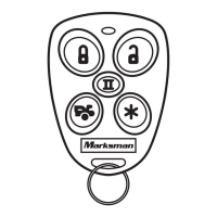
87
86
85
30
Orange Wire
(SPST ALA984H
Relay Not Supplied)
Output to Dome Light (+ or
-
)
To Constant +12 Volts
Input to Relay (+ or
-
)
Insert Orange Wire into
the First Socket
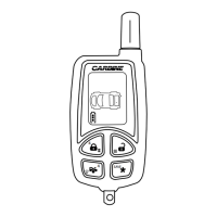
Red Wire
ALA-RPT
Relay Pack
Orange Wire
Output to Dome Light (+ or
-
)
Purple Wire
Input to Relay (+ or
-
)
Insert Black Wire into the First Socket
Insert Red Wire into the Second Socket
Black Wire
Dome Light Supervision Using Optional ALA-RPT Relay Pack:
Dome Light Supervision Using Optional 30 Amp Relay:
11
87
86
85
30
White Wire with
Black Stripe
(SPST ALA984H
Relay Not Supplied)
Output to
Power Trunk Switch
To Constant +12 Volts
Input to Relay (+ or
-
)
Insert White Wire with Black Stripe
into the Eighth Socket
#2 Button Power Trunk Activation Using Optional 30 Amp Relay
Step 4: Optional Accessory Connections (continued)
M5A-IM 9/10/04 9:27 AM Page 11