MGT 240M–1200M 3” NXT2 - SYSTEM 14 DEMAND
INSTALLATION
10
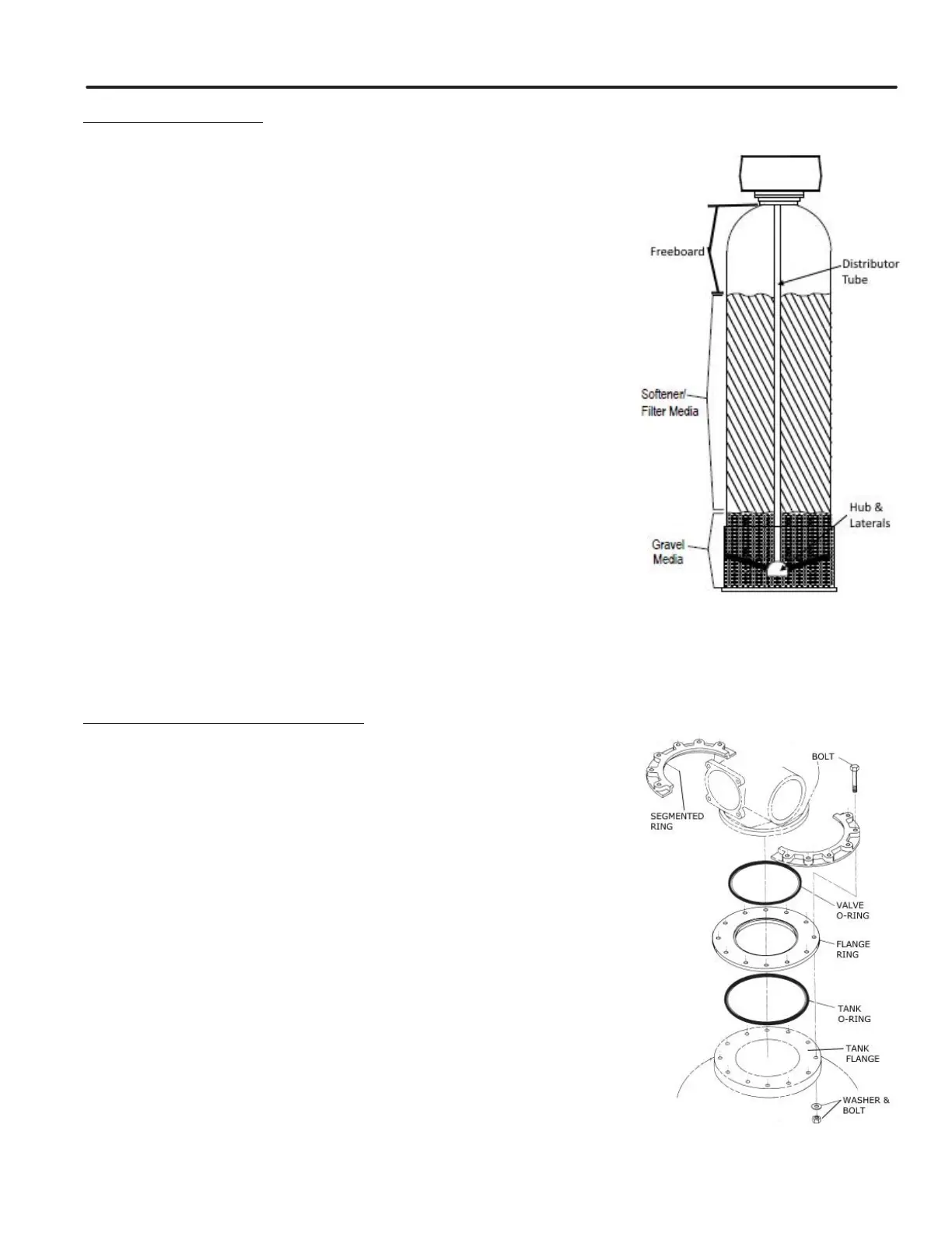
LOAD SOFTENER TANK
IMPORTANT: Be sure to visually inspect the lower laterals prior to loading
the media. Check to make sure each lateral is rmly threaded into the hub
1. Fill tank(s) approximately 1/3 full of water using a hose, bucket, etc. Plug the
PVC distributor manifold pipe using a plastic cap, cork, rag, etc. NO gravel or
resin should go into this distributor manifold pipe.
2. Verify the distributor manifold is center in the tank with the distributor resting
on the bottom of the tank. Verify the riser pipe is still plugged.
NOTE: Reference the specication table in the front of this manual for the
correct quantities of gravel and resin. Note that these quantities are for each
tank. Make sure you have the required amounts on site before you begin.
3. With care not to damage any lateral, pour in the gravel provided for each
tank through the top opening in the tank and level out evenly. This will cover
the distributor assembly.
NOTE: Wetting the gravel in the bags before loading will eliminate the normal
amount of dust.
4. When gravel is loaded and leveling is completed, proceed as follows:
5. With the distributor riser pipe still plugged, add the proper amount of resin
supplied for each tank through the top opening in the tank.
Caution: The softener resin is very slippery. Take care when stepping on any
pilled resin. Remove spilled resin from standing immediately.
6. When loading is complete, remove plastic cap, cork, or rag that was used to plug the distributor riser pipe. Be
careful not to let any foreign debris fall into the pipe. The result could be damage to system.
7. Repeat instruction steps 1-6 for each softener tank (if applicable).
MOUNT CONTROL VALVE ASSEMBLY
1. Verify that the distributor riser pipe is not plugged.
2. Lubricate the distributor o-ring on the bottom of the control valve with silicone.
3. Insert disperser into base of control valve. The base has a groove machined
into the inside of the anged part of the base to allow for the installation of
this disperser.
4. Place the tank o-ring and ange ring on the top of the tank. Line up the
bolt holes. Then place the valve o-ring on the ange ring.
5. Place the control valve onto the ange ring making sure the distributor riser
pipe slides easily through the distributor o’ring. Care must be taken not to
“nick” this o’ring as hard water leakage could result. Turn the control to align it
with the front of the tank.
6. Align the segmented rings with the holes in the ange ring and tank and use
the included bolts, washers, and nuts to secure the valve to the tank. Tighten
down the control valve to ensure positive o’ring seal at top of tank.
7. Repeat instruction steps 1-5 for each softener tank (if applicable)
 Loading...