MGT 240M–1200M 3” NXT2 - SYSTEM 14 DEMAND
OPERATION
19
SYSTEM OPERATION IN SERVICE
• The system operates as part of a multi-valve regeneration system.
• Each valve in the system will have an active ow meter input, even in stand by.
• The number of valves in service depends on the ow rate.
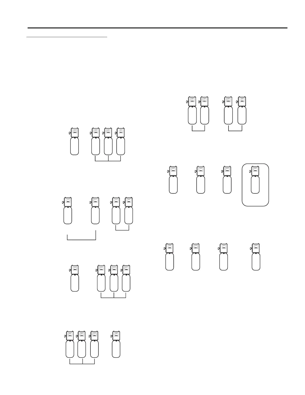
EXAMPLES OF A FOUR-UNIT SYSTEM:
Thesystemoperatesaspartofamulti-tankregeneration
system.Thisexampleappliestoeithera2,3or4tanksystem.
Eachtankinthesystemwillhaveanactiveowmeterinput,
eveninStandby.
ThenumberoftanksInServicedependsontheowrate.
Examples of a Four-Unit System:
1. OneTankisInServiceatalltimes(the"primarytank").
In Service
(Primary Tank)
Standby
1
234
2. Thetotalowratetotheprimarytankincreasedpastthe
rsttrippointprogrammedrate.Theowstayedpast
thetrippointdelayedtime.Thenexttank(leastvolume
remaining)changesfromStandbytoInService.Thisthen
splitsthetotalowbetweentwometers.
In Service
1 2 34
Standby
First Trip Point
(Primary Valve)
Total Flow Split
Between Two Meters
3. Theowratedemanddecreasedbelowthersttrippoint.
ThetankreturnstoStandby.
Standby
Flow Rate Demand
Below First Trip Point
(Primary Valve)
1 234
4. Totalowratedemandincreasedpastasecondtrippoint
programmedrate.Thesecondandthirdtank(leastvolume
remaining)changesfromStandbytoInService.Thetotal
owissplitbetweenthethreemeters.
Standby
Flow Split Between
Three Meters
12 3 4
5. ThethirdtankreturnstoStandbyasdemanddecreases
pastthesecondtrippoint.
Standby
Flow Split Between
Two Meters
12 34
6. TanksreturntoStandbyduetodecreasedtotalowrate
andtrippointsprogrammed.Thetankwiththemost
remainingvolumewillbethersttogointoStandby.
Full Capacity
4th in Standby
(Primary Valve)
3/4 Capacity
3rd in Standby
1 2 3 4
1/2 Capacity
2nd in Standby
1/4 Capacity
1st in Standby
7. Theprimarytankregenerates.Thenexttankwiththeleast
remainingvolumebecomesthenewprimarytank.Thetank
withthenextleastvolumeremainingwillbethersttrip
pointprogrammedrate.Tankscontinueoperatinginthis
order.
Full Capacity
4th in Standby
3/4 Capacity
3rd in Standby
1 2 3 4
1/2 Capacity
First Trip Point
Programmed Rate
1/4 Capacity
New Primary Tank
System Operation in Regeneration:
IftwotanksareInServiceandbothreach
VolumeRemaining=0,theothertwotankswillshiftfrom
StandbytoInService.Theleadtankwith
VolumeRemaining=0willstartRegeneration.Thesecond
tankwithVolumeRemaining=0willenterStandby.Ifow
increasespastthetrippointathirdtankneedstoenterIn
Service.ThetankinStandbywithVolumeRemaining=0will
shiftintoInServicetomaintainasteadyow.Operatingfor
extendedperiodsinthismodemaydegradethewaterquality.
 Loading...