_
5
_
Assembly
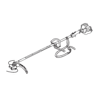
Assembling Engine and Drive Shaft Assembly
[Model
BC3021RS, BC4321H-RS
]
Attach the clutch drum housing to the engine using the four
screws supplied with the unit.
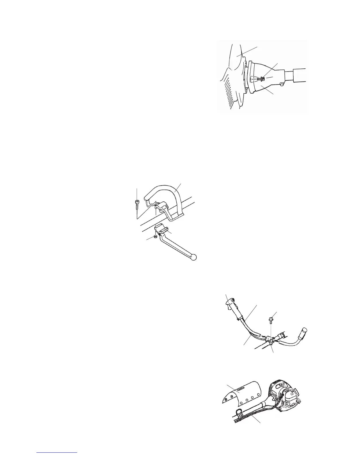
Loop Handle Installation
[Model BC2301RS, BC2601RS, BC3021RS]
1. Place the loop handle and the bottom clamp on the shaft assembly approximately 28cm(11 inches)
from the end of the stop switch/throttle trigger assembly.
2. Install the four screws and nuts. Tighten the screws evenly.
3. Reposition the loop handle up or down the drive shaft to the most comfortable position, but no closer
than 23 cm (9 inches) from the end of the stop switch/ throttle trigger assembly.
4. Tighten the screws and nuts.
Horn Handle Installation
[Model BC4321H-RS]
IMPORTANT: Be careful not to damage the throttle
cable and stop switch wires when you re-
move the horn handles from the carton.
1. Loosen the four screws on the top of the clamp bracket.
2. Insert the left and right horn handles into the clamp
bracket.
Note that the horn handle with the throttle trigger and
stop switch goes on the right-hand side of the Trimmer/
Brushcutter.
3. Adjust the horn handles to the desired position, then
tighten the four screws.
4. Lap and x the throttle cable and stop switch wires with
the pad as shown.
Engine
Clutch Drum Housing
Screw(4)
Bottom Clamp
Throttle Trigger and Stop Switch
Horn Handle
Screw (4)
Clamp Bracket
Stop Switch Wires
and Throttle Cable
Pad
Throttle Cable and
Stop Switch Wires
[BC2301RS, BC2601RS, BC3021RS]
[BC4321H-RS]
[BC4321H-RS]
Nut (4)
Loop Handle
Screw(4)