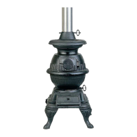
Masport F33-1 Freestanding Gas Stove 7
INSTALLATION IS TO BE CARRIED OUT
ONLY BY AN AUTHORISED PERSON
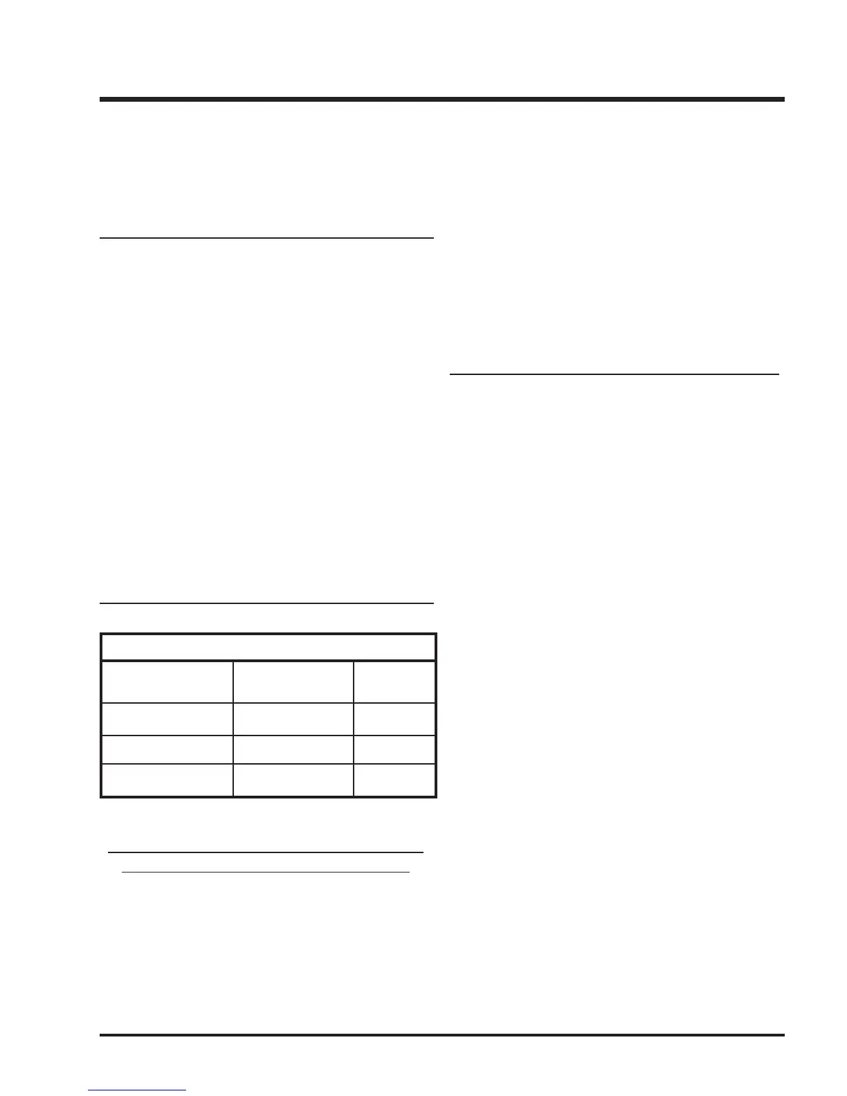
SYSTEM DATA
Natural Gas Propane
Injector size # 36 # 52
Input Rating 33 mj 33 mj
Manifold Pressure 0.8 kPa 2.38 kPa
INSTALLATION
DRAFT HOOD
The heater has a draft hood built into its back. It must not be
altered or obstructed, and the unit must be installed so that the
draft hood is in the same atmospheric pressure zone as the
combustion air inlet to the burner.
FLUING
This heater is a vented appliance and must be connected to a
chimney/flue in accordance with installation codes.
For your safety this heater is equipped with a flue safety switch.
This thermally actuated switch is located within the draft hood
and will detect either a blocked chimney or backdraft condition
where the chimney flow has reversed and will react by shutting
off the gas supply.
Note: The spill switch is manually resettable and comes
from the factory in the open position. Before trying
to start up the unit, make sure the red button on the
spill switch is pushed in.
Fluing Requirements
100mm diameter flue is required in accordance with AG 601,
NZS 5261 or any relevant local building codes. For altitudes
above 610m. we recommend that a minimum flue height of 3.6m.
is used.
GAS CONNECTION
The gas connection is a 1/2 inch BSP Male thread. The gas line
can be rigid copper pipe. Pipe size to ensure correct operating
pressure. For minimum and maximum supply pressure see the
System Data table below.
Note: During any pressure testing of the gas supply
piping system that exceeds test pressures of 3.45
kPa, this appliance and its individual shut-off valve
must be disconnected from the piping system. If
test pressures equal to or less than 3.45 kPa are
used then this appliance can be isolated from the
piping system by closing its individual manual shut-
off valve , if fitted, during the testing.
GAS PIPE PRESSURE TESTING
The appliance must be isolated from the gas supply piping
system by closing its individual manual shut-off valve during any
pressure testing of the gas supply piping system at test pres-
sures equal to or less than 3.45 kPa. Disconnect piping from
valve at pressures over 3.45 kPa.
The manifold pressure is controlled by a regulator built into the
gas control, and should be checked at the pressure test point.
Note: To properly check gas pressure, both inlet and
manifold pressures should be checked using the
valve pressure ports on the valve.
1) Make sure the valve is in the "OFF" position.
2) Loosen the "IN" and/or "OUT" pressure tap(s), turning
counterclockwise with a 1/8" wide flat screwdriver.
3) Attach manometer to "IN" and/or "OUT" pressure tap(s)
using a 5/16" ID hose.
4) Light the pilot and turn the valve to "ON" position.
5) The pressure check should be carried out with the unit
burning and the setting should be within the limits specified
on the safety label.
6) When finished reading manometer, turn off the gas valve,
disconnect the hose and tighten the screw (clockwise) with
a 1/8" flat screwdriver. Screw should be snug, but do not
over tighten.
 Loading...