8
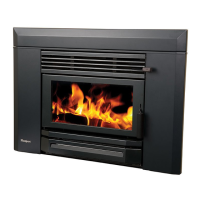
31. Remove the standard top rail of the fascia and replace it by the vented one. Remove the bottom
bar of the fascia and replace it by the vented bottom rail, taking care to trap the mains lead and
grommet between the left end of the bottom rail and the left fascia upright. If necessary,
replace the electrical connections at the rear of the fan switch (see installation manual) and
ensure that the earth wire is connected to the post behind the Masport badge on the left fascia
upright.
32. Connect the fan with help of a registered electrician as per instruction on page 14
33. Fit the fascia by offering it up to the heater about 15 mm above its final position and lowering
it, making sure the lip behind the top fascia rail engages in the slot at the top of the shielding
box. Fit the six retaining screws.
34. Fit the upper and lower fascia grilles and the firebox door as described in the
installation manual.
35. Ensure that the ceiling baffle, secondary air tube and the two side bricks and the two rear
bricks are in the correct position.
36. Finish the floor protector by installing an edge trim if desired.
NOTES FOR SPECIAL CONSTRUCTIONS & VARIATIONS :
CONCRETE FLOORS: The above instructions assume that the heater is being assembled on a heat
sensitive floor such as timber or particle board. Where the floor is not heat sensitive (e.g. concrete, the
insulating floor protector may be omitted. However, if heat sensitive floor coverings are fitted it will
be necessary to keep them at a safe distance. The most practical way to do this is to fix tiles to the
floor where the floor protector would normally be. This will make the top of the protector
approximately flush with the floor covering, so a larger floor protector will be needed. It must extend
out to 453 mm from the face of the front cladding material, with a minimum width of 965 mm. Refer
paragraph 6 and Fig 9.
EXTERNAL INSTALLATIONS: In the case where the enclosure is to be erected outside the house,
the shielding and flue installation details above will still apply. It is important to remember that the
aperture in the wall of the house will need to be sufficiently high to permit the installation of heat
resistant paneling in front of the heater to at least 1290 mm above the bottom of the shielding box
rails. Suitable foundations will be required to support the weight of the enclosure and the heater and
weatherproofing of the entire assembly will be necessary.
BRICK FACED INTERNAL ENCLOSURES:
Flue installation and clearance requirements are as detailed above. Brick wall construction will
normally require a cast concrete base slab, so this slab could be extended to provide the necessary
floor protection.
CAUTION: If local Building Requirements permit laying the concrete slab on top of a wooden floor, it
should be made of lightweight concrete and even then foundation support may be required. In any
case, the slab should be poured on top of one layer of Micore 160 board (covered with sheet plastic to
keep it dry) to prevent heat damage to the wooden floor. The top surface can be finished with bricks
or tiles etc. In all cases the floor protector dimensions must be as previously shown.
As before, the opening for the appliance in the front wall must be 737 nun wide and 719 mm high.
Note that the bricks above the opening must extend to at least 1290 mm above the bottom of the
shielding box rails.
Fit the shielding box and complete the installation as previously detailed for standard installations.
 Loading...
