5
STANDARD INSTALLATIONS- FLOOR TO CEILING ENCLOSURE:
1. Inspect the house construction at the proposed installation position to verify that the flue shield
(250mm diameter, plus 25mm clearance all around) can pass right up through the ceiling
space without requiring the removal of essential roof or ceiling support beams. The flue cen-
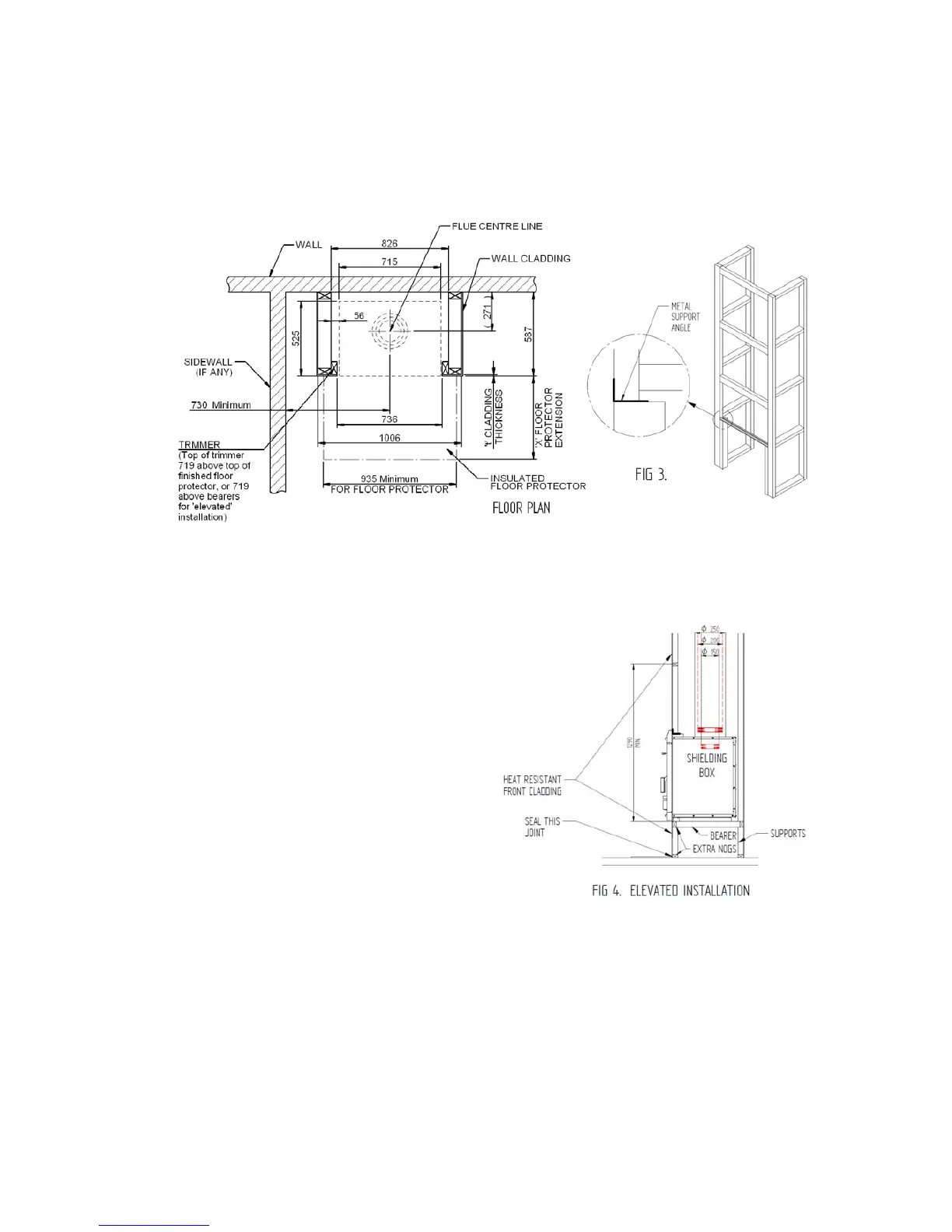
terline will be 271 mm out from the rear wall and it must be at least 730mm distant from any
side wall. (See Fig. 2).
Fig. 2
FLOOR PLAN
2. Drop a plumb line from the ceiling to the floor to verify the centerline and cut a hole at least
300mm square through the ceiling on this centerline. If preferred, there may be no ceiling
inside the fireplace enclosure. (See step 12)
3. Ensure that there are suitable nogs at either the ceiling or roof level (or both) to provide
anchorage for the outer flue heat shield
bracing angles.
4. Frame up the enclosure using nominal 90
by 45 dressed timber, verifying that it will be
on the flue centerline. (See Fig. 3). The
overall depth of the frame should be (587 — t)
mm, where 't' is the cladding thickness. The
distance between the trimmers (where the
assembled shielding box will fit), should be
737mm. The overall width of the enclosure
frame shown is the minimum required, but if
desired it may be larger. The trimmers do not
run the full height, but end 719 mm above the
finished top face of the floor protector (or 719
mm above the top of the bearers if the heater
is 'elevated'). Refer to paragraph 6 for floor
protector thickness options and the
advantage of 'elevated' installations. Fix the
metal support angle across the tops of the
trimmers to provide support and fixing for the
front heat resistant cladding. (See Fig. 3).
5. For an 'elevated' installation, fix two extra nogs (90x45x737 mm) across the front opening
of the enclosure, one at the bottom and the other at the desired 'elevation' height. (See Fig. 4).
These extra nogs will carry the front cladding below the heater. Fix two 90 x 45 bearers
running from front to back behind the top extra nog, 240 mm each side of the centerline to
support the shielding box rails. The bearer tops must be flush with the top of the top extra
nog. Provide support at the rear of the bearers to carry the appliance. (See Fig. 4). The
shielding box rails can sit directly on the bearers. No insulation is necessary. The usual three
nogs may be fixed at each side of the enclosure. At the front, the lowest wooden nog N must
have its lower face at least 1290 mm above the top of the floor protector (or 1290 mm
above the bearers for an elevated installation). Further wooden nogs can be fitted at the front
above this one.
6. The side cladding for the enclosure may be Gib board or any other wall cladding material.
For ease of flue installation, leave the cladding off at least one side until the flue system has
been installed.
 Loading...