Masport Inbuilt Gas Fires - 10 - 19/11/04
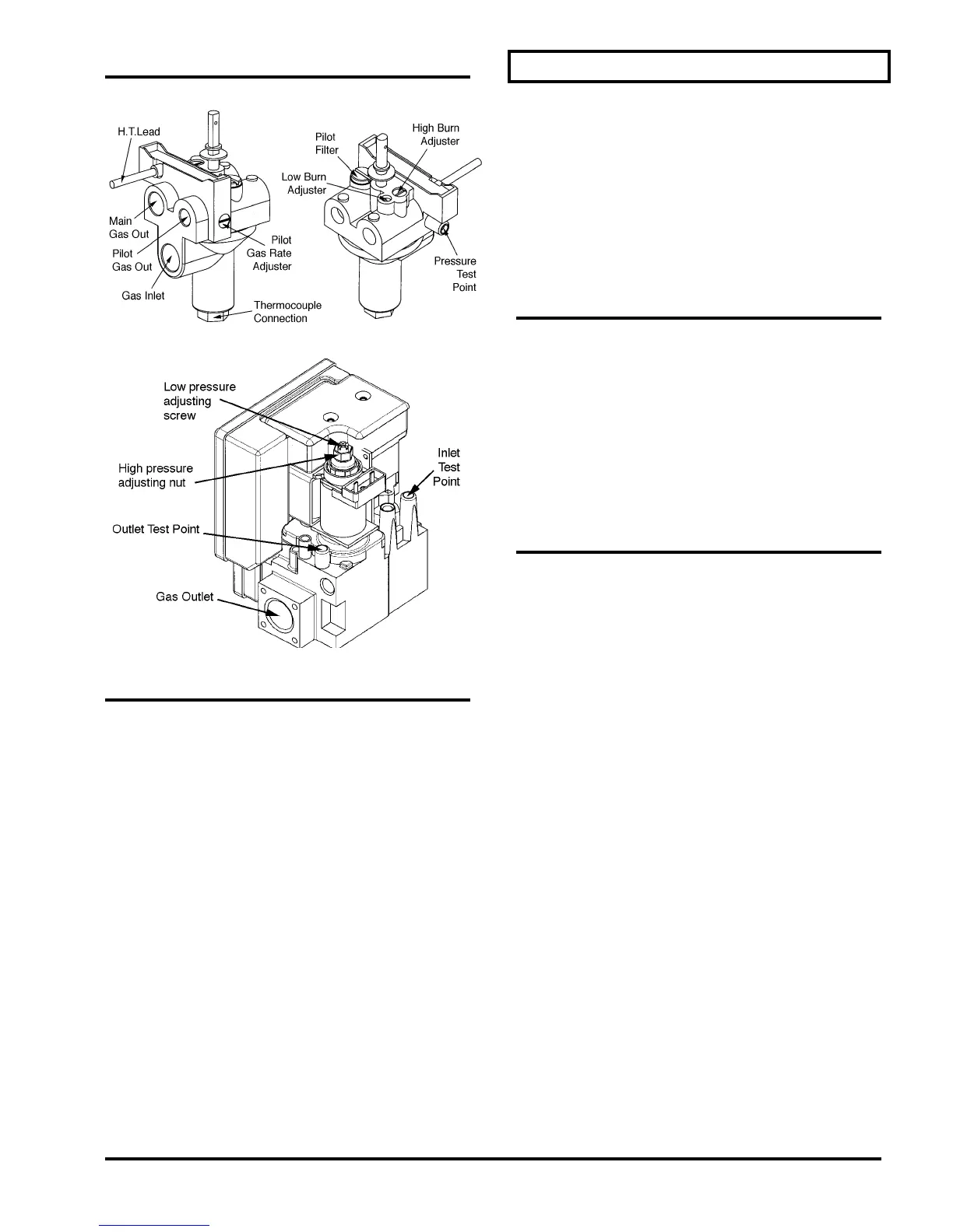
VALVE DETAILS
Piccolo
EIS and ECS Models
OPTIONAL REMOTE CONTROL
INSTALLATION (EIS Models Only)
Use the Optional Masport Remote Control Kit (the
Climate Pilot) approved for this unit. Use of other
systems may void your warranty.
The remote control kit comes with a hand held
transmitter, and a receiver.
1) Choose a convenient location to install the receiver
(protection from extreme heat is very important).
Run wires from the appliance to that location.
2) Connect the two wires to the terminals at the front
of the control box (behind the bottom louvre or
grille) in place of the jumper wire already installed
there. (Refer to instructions supplied with the
remote control for detailed installation instructions)
Remote Control Thermostat (RF)
Masport Part Number 791397
ZERO CLEARANCE INSTALLATION
SEE PAGE 5 FOR INSTALLATIONS IN
MASONRY FIREPLACE
REQUIREMENTS FOR INSTALLING
IN TIMBER STRUCTURES
Piccolo, Sofia and Madrid heaters can be installed in
timber structures provided that the correct shielding
cabinet is used. The fascia requires modifications
also, and a special flue system is required. Because
the fascia lifts the heater up from floor level, no floor
protector (hearth) is needed. Conversion kits
appropriate to the model are available from Masport.
WARNING: The stand-off angles on the sides and rear of
the outer cabinet are fitted to ensure a safe clearance to
combustible materials. The angles must not be
removed. No combustible framing material must be less
than 35mm above the top of the outer cabinet.
All Masport heaters are tested to NZ and Aust.
Standards. Clearances are for fire hazard only. Wall
surfaces directly above the heater may reach 85 degrees
C, so materials such as wallpaper and water based paint
may be adversely affected. For durability of finishes and
surfaces, contact the relevant manufacturer. Masport
accepts no responsibility for the deterioration of
surfaces or finishes.
PROCEDURE FOR IN-ROOM
INSTALLATIONS
1. Inspect the house construction to verify that the
150 mm diameter flue shield can pass right up
through the ceiling space without requiring the
removal of essential support beams. The flue
centreline will be 363mm back from the finished
front face of the enclosure. With the heater parallel
to the wall, and the enclosure built to its minimum
allowable depth, the flue centreline will be 217mm
from the wall. With the heater parallel to the wall,
any heat sensitive side wall must be at least
520mm from the heater centreline. If the enclosure
is to be at 45° in the corner of the room, and is bu ilt
to its minimum allowable depth, the face of the
enclosure will be 935mm out from the corner and
the flue centreline will be 600mm out from the
corner.
2. Drop a plumb line from the ceiling to the floor to
establish a flue centreline as detailed above, and
cut and nog a hole at least 200mm square through
the ceiling on this centreline. The ceiling inside the
enclosure may be removed entirely, if desired, and
it must be removed if it will be less than 1600mm.
above the top of the outer steel cabinet. See step
10.
3. Frame up the enclosure as shown in Fig. 1. The
frame should provide a recess 710mm wide and at
least 580mm deep (measured from the face of the
cladding material or from any tiles etc. that may be
fixed to the cladding material). The overall width of
the frame must be not less than 1040mm to
accommodate the fascia width and to ensure a safe