Masport Inbuilt Gas Fires - 18 - 19/11/04
Malfunctioning due to improper log placement is not
covered under warranty.
GLASS GASKET
If the glass gasket requires replacement use 25mm flat
glass gasket for the Flush Front, Masport part number
786774 or 10mm flat glass tape for the curved window
Masport part number 790229.
GOLD-PLATED TRIM
The 24-carat gold plated finish on the trim requires
little maintenance, needing only be cleaned with a
damp cloth. DO NOT use abrasive materials or
chemical cleaners, as they will harm the finish and
void the warranty. Clean any fingerprints off before
turning the unit on.
GLASS REPLACEMENT
Your Masport stove is supplied with high temperature,
5 mm Neoceram ceramic glass that will withstand the
highest heat that your unit will produce. In the event
that you break your glass by impact, purchase your
replacement from an authorised Masport dealer only,
and follow our step-by-step instructions for
replacement.
Bay Glass Removal
1) Remove the window from the unit (refer to removal
instructions on page 9) and place on a soft surface
to prevent scratching.
2) Remove the nuts holding the glass retainers in
place.
3) Remove the glass retainers.
4) Replace the glass.
5) Reverse the previous steps, replace the retainers
and fasten with the nuts but do not over tighten, as
this can break the glass.
6) Refit the window to the fire and check the seal.
FLUSH GLASS REPLACEMENT
Remove the glass by following the instructions on page
8. Fit the new glass, replacing the gaskets if necessary.
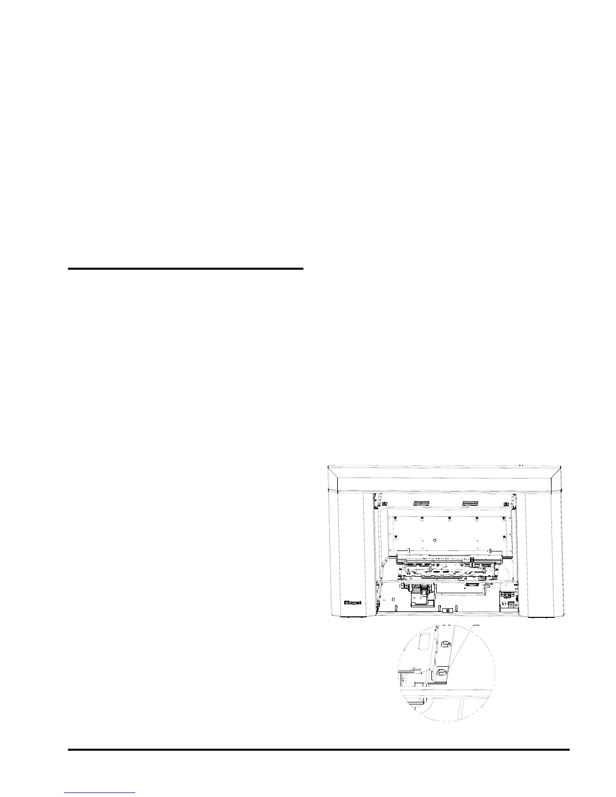
FAN MAINTENANCE
If your fan requires maintenance or replacement,
access is via the panel on the rear wall of the firebox.
Note: The unit MUST NOT be operated without the fan
access panel securely in place.
To remove fan:
1) Turn the unit and/or pilot off and allow it to cool to
room temperature.
2) Disconnect the power source to the fire.
3) Remove glass front (see pages 8 & 9).
4) Remove logs and embers (see page 9).
5) Remove the burner (two screws at the front, refer
to diagram on page 18).
6) Loosen the screws securing the rear fan access
panel in place. Lift and withdraw the panel passing
the keyhole slots over the screw heads.
7) Working below the burner tray, remove the fan
shipping nuts.
8) Unplug the fan lead from the plug on the control
box (EIS and ECS models). On Piccolo models
unplug the fan adaptor loom from the fan switch
loom.
9) On EIS models disconnect the two push on
connectors at the thermodisc terminals below the
burner tray.
10) Lift and withdraw the fan assembly from its
mounting pins on the base of the fire. The fan will
come out through the access panel.
11) Reassemble in the reverse order.