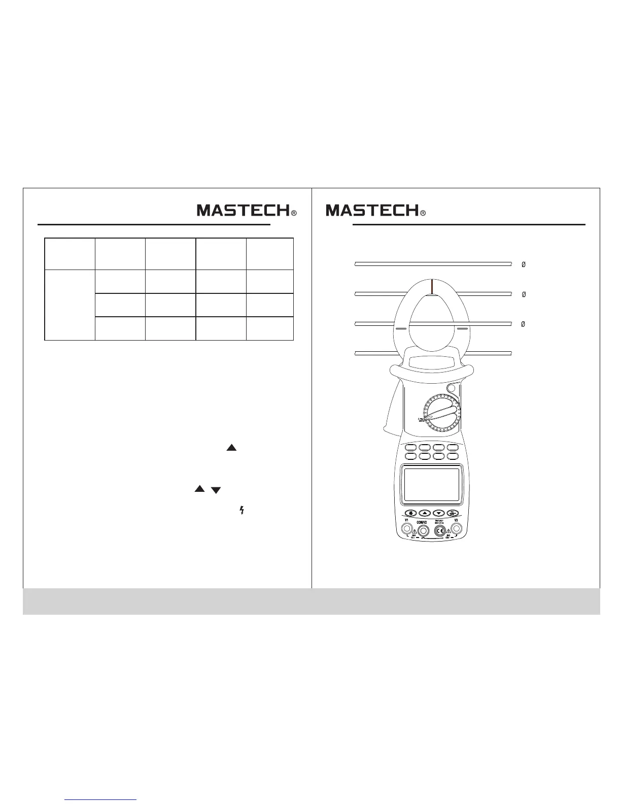
Switch
Inputting
terminal V1
Inputting
terminal V2
Inputting
terminal V3
Test object
V~
V1 socket
COM/ V2
socket
COM/ V2
socket
COM/ V2
socket
N/A
N/A
V3 socket
1-phase
2-phase
3-phase
13 14
1.According to the connection mode as above Table ,
switch the function switching knob to V~, select
corresponding sockets from V1, V2, or V3 terminal,
and insert the test wire.
2.Connect the two test probes V1, V2 to the power
source or load to be tested. The meter will automatically
test and display the result, and the present harmonics
percentage will be shown on the following line.
3.Under voltage test mode, press SET button to show
”Auto V” and “Auto A” on LCD, and press to select a
proper voltage range, and then press SET to return.
4.Press MODE button to show harmonics percentage
on LCD, and the total harmonic distortion ratio F and R
will be cyclically displayed. Press / button to
display value of each measurement of the harmonic.
5.When input voltage is greater than 50 V, “ ” sign
will be shown on LCD, prompting you to pay attention
to safety.
AC-current (A) measurement
NEUTRAL
3
2
1
V1 socket
V1 socket