EasyManua.ls Logo

Mastech MS8265 - User Manual

Mastech MS8265
16 pages
Print Icon
To Next Page IconTo Next Page
Loading...
MS8265
DIGITAL MULTIMETER
OPERATOR'S
INSTRUCTION MANUAL
MS8265
ON/OFF
HOLD
LIGHT
10A
COM
FUSED,10A MAX
RESETTABLE
750V
1000V
MAX
600V CAT III
1000V CAT II
hFE
mA
F
Hz
10
200m
200m
2m
10
hFE
200m
2
20
200
1000
750
200
20
2
20
200M
200K
20K
2K
200
200μ
20μ
2μ
200n
20n
2m
20M
2M
KHz
Question and Answer IconNeed help?

Do you have a question about the Mastech MS8265 and is the answer not in the manual?

Overview

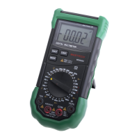
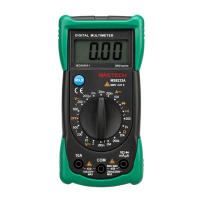
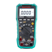
The MASTECH MS8265 is a digital multimeter designed for various electrical measurements, complying with IEC 1010-1 (61010-1@IEC: 2001), CAT. II 1000V, and CAT. III 600V over-voltage standards. It features a 4 1/2 digit LCD display with automatic indication of functions and symbols, and an auto-power-off function to conserve battery life.

Function Description:

The multimeter offers a wide range of measurement functions including AC and DC voltage, resistance, diode test, continuity check, capacitance, transistor (hFE), frequency, and AC/DC current.

  • Voltage Measurement (AC and DC): The device measures both AC and DC voltages. DC voltage ranges are 200.00mV, 2.0000V, 20.000V, 200.00V, and 1000.0V. AC voltage ranges are 2.0000V, 20.000V, 200.00V, and 750.0V. To measure voltage, the rotary switch is set to the appropriate range, and test leads are connected to the COM and V terminals. The polarity of the red test lead connection is indicated during DCV measurements. Unstable displays may occur at DC200mV and AC2V ranges, and in such cases, shorting the V and COM terminals should result in a zero display.

  • Resistance Measurement: Resistance ranges include 200.00Ω, 2.0000kΩ, 20.000kΩ, 200.00kΩ, 2.0000MΩ, 20.000MΩ, and 200.00MΩ. The rotary switch is set to the proper range, and test leads are connected to the COM and Ω terminals. For low resistance measurements, it's recommended to short the test leads and subtract their resistance for better accuracy. The 2MΩ range should not be used for in-circuit resistance measurements to avoid forward-biasing silicon diode or transistor junctions. Readings on 20MΩ and 200MΩ ranges may take a few seconds to stabilize. An open circuit displays "1".

  • Diode Test: This function checks diodes and other semiconductor devices by sending a current through the junction and measuring the voltage drop. A good silicon junction typically drops between 0.5V and 0.8V. The rotary switch is set to the diode range, and test leads are connected to the COM and diode terminals. For forward-bias readings, the red lead is placed on the anode and the black lead on the cathode. A reversed connection displays "1".

  • Continuity Check: The continuity check sounds a beeper if a circuit is complete (below approximately 50Ω). The rotary switch is set to the continuity range, and the yellow key is pressed twice to activate the function. Test leads are connected to the COM and Ω terminals.

  • Capacitance Measurement: Capacitance ranges are 20.000nF, 200.00nF, 2.0000µF, 20.000µF, and 200.00µF. The rotary switch is set to the proper range, and test leads are connected to the COM and capacitance terminals (or using the special Multi-Function Socket). The meter may take a few seconds to stabilize for high capacitance measurements. For measurements less than 20nF, subtracting the residual capacitance of the meter and leads improves accuracy.

  • Transistor (hFE) Measurement: The hFE range is used to measure the approximate hFE value of transistors (0-1000). The rotary switch is set to hFE, and the special multi-function socket's "com" and "+" plugs are connected to the COM and hFE terminals. Transistor leads are inserted into the appropriate holes (Emitter, Base, Collector) based on whether it's an NPN or PNP type.

  • Frequency Measurement: The device measures frequency up to 20kHz. The rotary switch is set to the 20kHz range, and test leads are connected to the COM and Hz terminals.

  • Current Measurement (AC and DC): DC current ranges are 2.0000mA, 200.00mA, and 10.000A. AC current ranges are 2.0000mA, 200.00mA, and 10.000A. To measure current, the circuit power is turned off, high voltage capacitors are discharged, and the rotary switch is set to the proper range. Test leads are connected to the COM terminal and either the mA or 10A terminal, depending on the expected current. The circuit path is then broken, and the meter is connected in series. For measurements greater than 5A, a maximum ON time of 4 minutes is recommended, followed by 10 minutes OFF.

Important Technical Specifications:

  • Environment Conditions: 1000V CAT. II and 600V CAT. III, Pollution degree 2, Altitude < 2000m.
  • Operating Temperature: 0~40°C (32~122°F) at <80% RH, <10°C non-condensing.
  • Storage Temperature: -10~60°C (14~140°F) at <70% RH, battery removed.
  • Temperature Coefficient: 0.1(specified accuracy)/°C (<18°C or >28°C).
  • MAX. Voltage: 750V AC rms or 1000V DC between terminals and earth ground.
  • Fuse Protection: Resettable fuse (F400mA/250V) for capacitance, temperature, mA, and hFE measurements. 10A range is protected by an F10A/250V fuse.
  • Sample Rate: 3 times/sec for digital data.
  • Display: 4 1/2 digits LCD display.
  • Over Range Indication: LCD displays "1".
  • Low Battery Indication: " " symbol displayed.
  • Polarity Indication: " - " displayed automatically.
  • Power Source: 9V battery (NEDA 1604, 6F22, or 006P).
  • Dimensions: 195(L) x 92(W) x 55(H) mm.
  • Weight: Approx. 380g (battery included).
  • Input Impedance (Voltage): 10MΩ.
  • Overload Protection (Resistance, Frequency, Continuity, Diode): PTC resistor protects against permanent over voltages of up to 250V.

Accuracy Specifications (at 18°C to 28°C, 0% to 75% RH):

  • DC Voltage:
    • 200mV: ±(0.05% of rdg +5 digit)
    • 2V, 20V, 200V: ±(0.1% of rdg +5 digit)
    • 1000V: ±(0.15% of rdg +5 digits)
  • AC Voltage (50-60Hz):
    • 2V: ±(0.5% of rdg +15 digits)
    • 20V, 200V: ±(0.8% of rdg +15 digits)
    • 750V: ±(1.0% of rdg +15 digits)
  • AC Voltage (40-400Hz):
    • 2V, 20V: ±(1.0% of rdg +15 digits)
    • 200V: ±(1.0% of rdg +50 digits)
    • 750V: ±(1.2% of rdg +50 digits)
  • Frequency: ±(1.5% of rdg +15 digits)
  • Resistance:
    • 200Ω, 2kΩ, 20kΩ: ±(0.5% of rdg +10 digits)
    • 200kΩ, 2MΩ, 20MΩ: ±(0.5% of rdg +5 digits)
    • 200MΩ: ±[5.0% of rdg +20 digits]
  • Capacitance: ±(4.0% of rdg +20 digits)
  • DC Current:
    • 2mA: ±(0.5% of rdg +10 digits)
    • 200mA, 10A: ±(2.0% of rdg +20 digits)
  • AC Current:
    • 2mA: ±(0.8% of rdg +20 digits)
    • 200mA: ±(1.2% of rdg +20 digits)
    • 10A: ±(2.5% of rdg +50 digits)

Usage Features:

  • Keypad:
    • ON/OFF: Turns the meter on or off.
    • HOLD: Enters and exits Data Hold mode, which freezes the current display value.
    • LIGHT: Turns the backlight on for approximately 5 seconds before auto-off.
  • Misconnection Alarm: The meter is equipped with sound and light alarms to warn against incorrect test lead connections for V/Ω/Hz, mA/hFE, and 10A ranges. This helps prevent damage and ensures proper setup.
  • Battery Saver: The meter automatically turns off after approximately 30 minutes of inactivity to save battery life.
  • Accessories: Includes a user's manual, test leads, and a special multi-function socket.

Maintenance Features:

  • General Maintenance:
    • Periodically wipe the case with a damp cloth and mild detergent; avoid abrasives or solvents.
    • Dirt or moisture in the terminals can affect readings. To clean, turn off the meter, remove test leads, shake out dirt, and use a swab with a cleaning/oiling agent (like WD-40) to insulate terminals from moisture.
    • Do not attempt to repair or service the meter unless qualified and with relevant information.
    • Always remove test leads and any input signals before opening the case.
  • Battery Replacement:
    • Replace the 9V NEDA battery (6F22) when the low battery indicator (" ") appears to avoid false readings and potential electric shock.
    • Before replacing, turn off the meter, disconnect test leads and any connectors from the circuit under test, and remove test leads from the input terminals.
    • Unscrew the two screws on the battery cover, remove the cover, replace the old battery with a new one, and then resecure the cover.
  • Protection Mechanisms:
    • Fused by a resettable fuse (F400mA/250V) for capacitance, temperature, mA, and hFE measurements.
    • A PTC resistor protects against permanent over-voltages up to 250V during resistance, frequency, continuity, and diode test measurements.

Safety Precautions:

  • Always observe normal safety rules regarding electric current and proper use of the multimeter.
  • Use only the supplied test probes and ensure they are in good condition.
  • Avoid using the meter if it or the test leads appear damaged.
  • Operate the meter only as specified in the manual to maintain protection.
  • Exercise extreme caution around bare conductors or bus bars.
  • Do not operate the meter in explosive gas, vapor, or dust environments.
  • Verify meter operation by measuring a known voltage.
  • Use proper terminals, function, and range for measurements.
  • When the value to be measured is unknown, start with the highest possible range or use autoranging mode.
  • Do not exceed maximum input limits.
  • Avoid touching unused terminals when the multimeter is connected to measurement circuits.
  • Be cautious when working with voltages above 60Vdc or 30Vac rms due to shock hazards.
  • Keep fingers behind finger guards when using probes.
  • Connect the common test lead first, then the live test lead; disconnect in reverse order.
  • Disconnect test leads from the circuit before changing functions.
  • For DC functions, verify AC voltages first to avoid improper readings and shock risk.
  • Disconnect circuit power and discharge high-voltage capacitors before testing resistance, continuity, diodes, or capacitance.
  • Never perform resistance or continuity measurements on live circuits.
  • Before measuring current, check the meter's fuse and turn off circuit power.
  • In TV repair or power switching circuits, use a TV filter to attenuate high amplitude voltage pulses.
  • Do not measure voltages above 600V in Category III or 1000V in Category II installations.
  • Do not operate the meter with the case (or part of the case) removed.
  • Be aware that strong radiated radio-frequency electromagnetic fields (approx. 3V/m) may influence measuring accuracy.

Mastech MS8265 Specifications

General IconGeneral
BrandMastech
ModelMS8265
CategoryMultimeter
LanguageEnglish

Related product manuals