9
Lowes.com/masterforge
ASSEMBLY INSTRUCTIONS
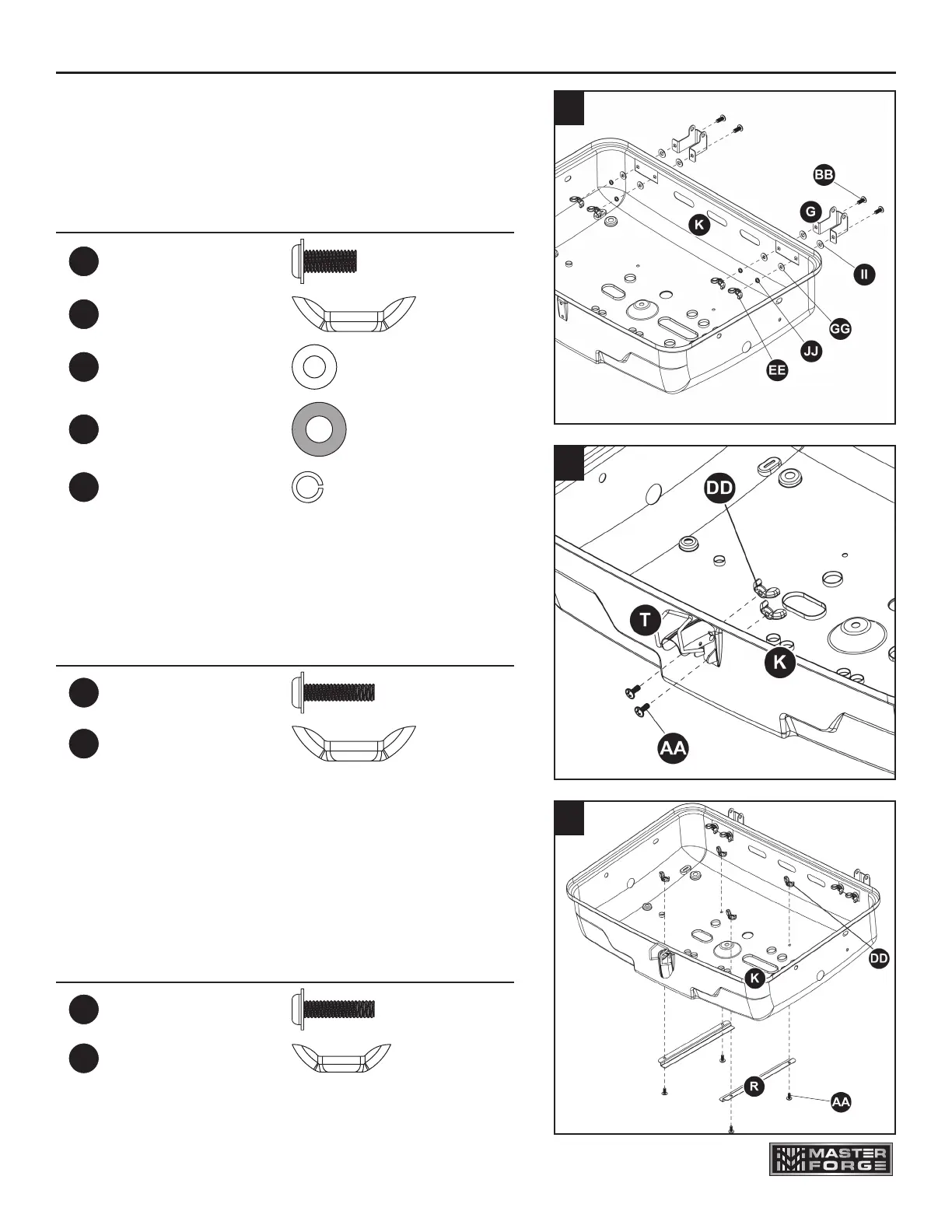
5. Attach the grease tray supports (R) to the bottom
bowl (K) using two sets of two M4 x 10 mm small
screws (AA) and two M4 wing nuts (DD).
Hardware Used
AA
M4 x 10 mm Screw x 4
DD
M4 Wing Nut x 4
3. Attach the bottom hinges (G) to the bottom bowl (K)
using four sets of M5 x 12 mm small screws (BB),
6 mm heat resistant washers (II), 5 mm washer
(GG), 5 mm lock washers (JJ) and M5 wing nuts
(EE).
Hardware Used
BB
M5 x 12 mm
Small Screw
x 4
EE
M5 Wing Nut x 4
GG
5 mm Washer x 4
II
6 mm Heat
Resistant Washer
x 4
JJ
5 mm
Lock Washer
x 4
3
4. Attach the lock (T) to the bottom bowl (K) using two
M4 x 10 mm small screws (AA) and two M4 wing
nuts (DD).
Hardware Used
AA
M4 x 10 mm Screw x 2
DD
M4 Wing Nut x 2
4
5