Logix Control Valve:
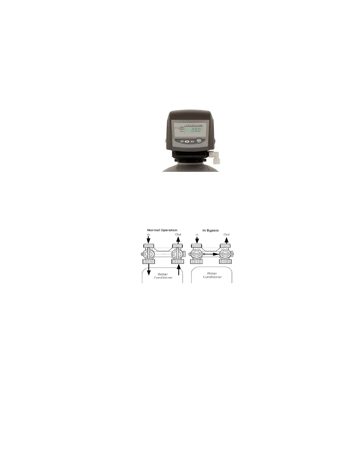
1. When facing the front of the Logix timer, the inlet connection (Figure 1)
is located on the left and the outlet connection is on the right. The
control valve's inlet and outlet connections are either 1” copper or PVC
equipped with gasket and nut.
Figure 1
Install the 263 bypass valve (See Figure 2) with inlet and outlet handles
facing upward. Place gasket into nut and secure 1” copper or PVC tail
piece with a nut. Repeat the procedure for the outlet connection.
DO NOT OVERTIGHTEN THE NUT.
Figure 2
2. The control valve's drain connection is 3/4" npt and is located on the
back of the bypass valve.
3. Turn the control valve upside down and ensure that the control valve
distributor o'rings are in place. The o’rings are lubricated with silicone
at the factory.
4. Fill mineral tank with water before installing control valve.
5. Place the control valve onto the distributor pipe.
6. Thread the control valve hand tight to 20 foot pounds!
DO NOT OVERTIGHTEN!
**DO NOT USE PETROLEUM!**
**USE ONLY SILICONE **