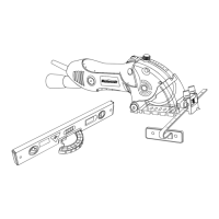
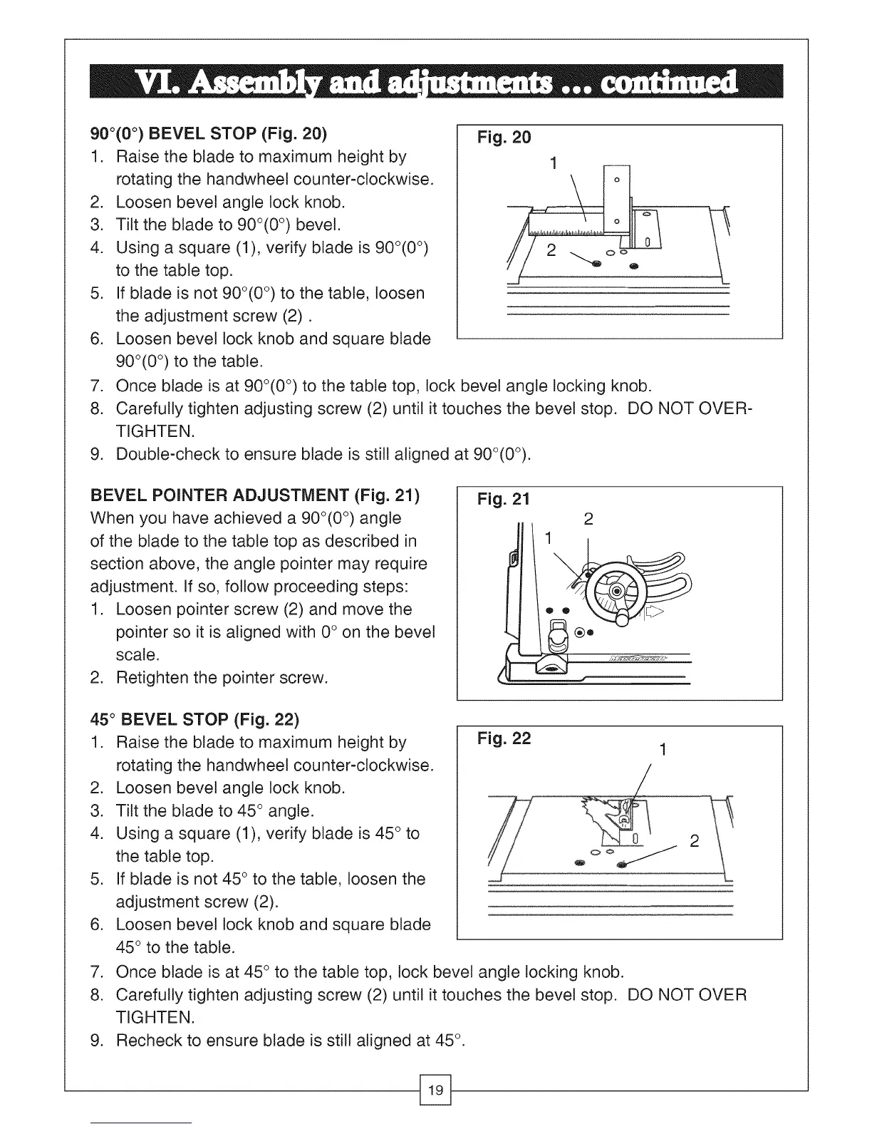
900(0°) BEVEL STOP (Fig. 20)
1. Raise the blade to maximum height by
rotating the handwheet counter-clockwise.
2. Loosen bevel angle lock knob.
3. Tilt the blade to 900(0 °) bevel.
4. Using a square (1), verify blade is 900(0 °)
to the table top.
5. If blade is not 900(0 °) to the table, loosen
the adjustment screw (2).
6. Loosen bevel tock knob and square blade
900(0 °) to the table.
Fig. 20
1
2
7. Once blade is at 90o(0 °) to the table top, tock bevel angle locking knob.
8. Carefully tighten adjusting screw (2) until it touches the bevel stop. DO NOT OVER-
TIGHTEN.
9. Double-check to ensure blade is still aligned at 90°(0°).
BEVEL POINTER ADJUSTMENT (Fig. 21)
When you have achieved a 90o(0 °) angle
of the blade to the table top as described in
section above, the angle pointer may require
adjustment. If so, follow proceeding steps:
1. Loosen pointer screw (2) and move the
pointer so it is aligned with 0° on the bevel
scale.
2. Retighten the pointer screw.
Fig. 21
2
45 ° BEVEL STOP (Fig. 22)
1. Raise the blade to maximum height by
rotating the handwheel counter-clockwise.
2. Loosen bevel angle lock knob.
3. Tilt the blade to 45 ° angle.
4. Using a square (1), verify blade is 45 ° to
the table top.
5. If blade is not 45 ° to the table, loosen the
adjustment screw (2).
6. Loosen bevel lock knob and square blade
45 ° to the table.
Fig. 22
2
7. Once blade is at 45 ° to the table top, lock bevel angle locking knob.
8. Carefully tighten adjusting screw (2) until it touches the bevel stop. DO NOT OVER
TIGHTEN.
9. Recheck to ensure blade is still aligned at 45 °.