WARNING: TO AVOID INJURY FROM AN ACCIDENTAL START, MAKE SURE THE
SWITCH IS IN THE "OFF" POSITION, THE REMOVABLE KEY IS REMOVED AND
THE PLUG IS NOT CONNECTED TO THE POWER SOURCE OUTLET.
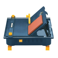
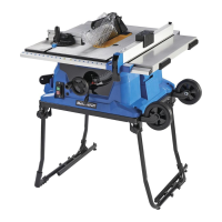
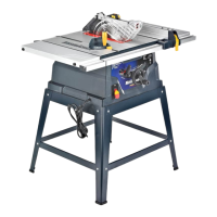
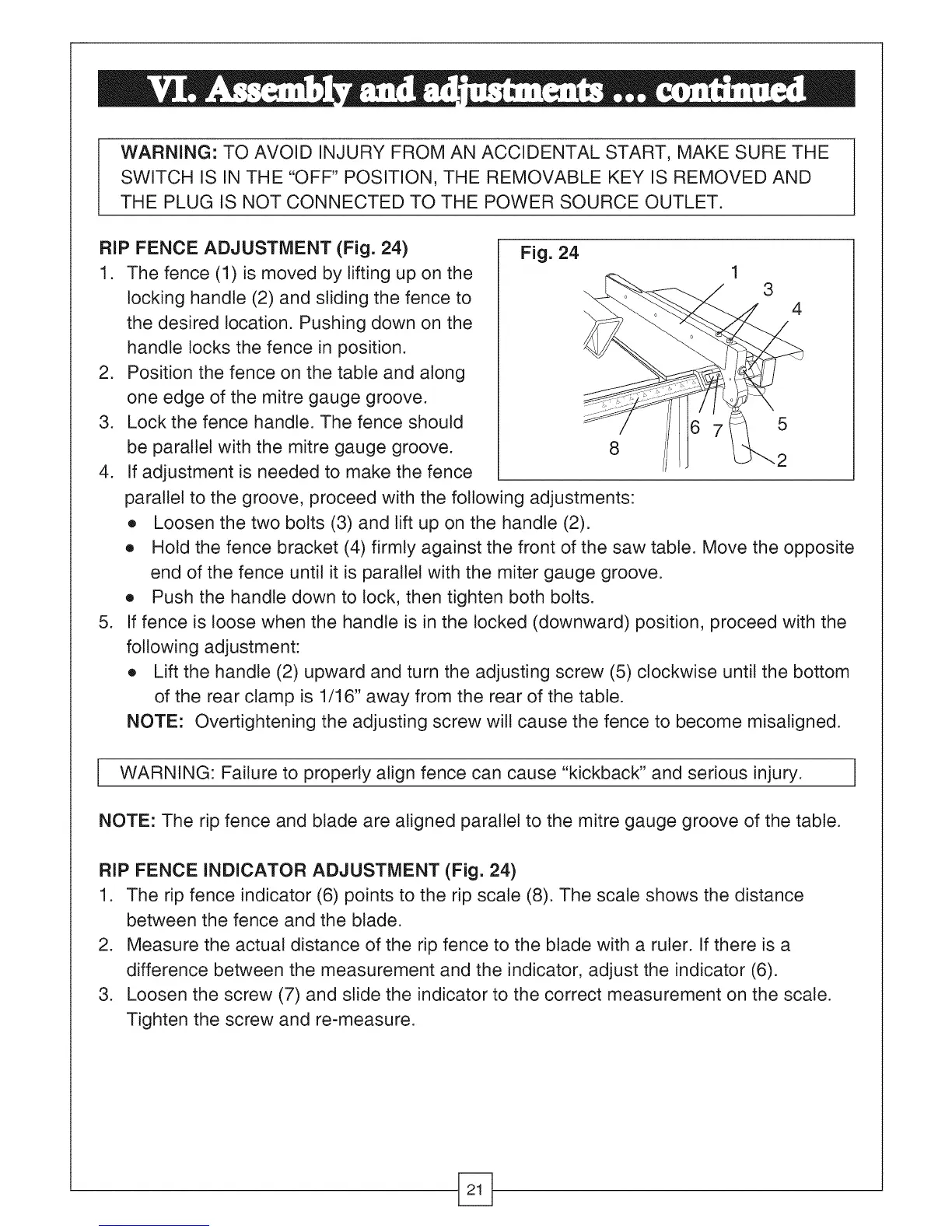
RIP FENCE ADJUSTMENT (Fig. 24)
1. The fence (1) is moved by lifting up on the
locking handle (2) and sliding the fence to
the desired location. Pushing down on the
handle locks the fence in position.
2. Position the fence on the table and along
one edge of the mitre gauge groove.
3. Lock the fence handle. The fence should
be parallel with the mitre gauge groove.
4. If adjustment is needed to make the fence
.
Fig. 24
1
3
4
5
2
parallel to the groove, proceed with the following adjustments:
e Loosen the two bolts (3) and lift up on the handle (2).
e Hold the fence bracket (4) firmly against the front of the saw table. Move the opposite
end of the fence until it is parallel with the miter gauge groove.
e Push the handle down to lock, then tighten both bolts.
If fence is loose when the handle is in the locked (downward) position, proceed with the
following adjustment:
e Lift the handle (2) upward and turn the adjusting screw (5) clockwise until the bottom
of the rear clamp is 1/16" away from the rear of the table.
NOTE: Overtightening the adjusting screw will cause the fence to become misaligned.
WARNING: Failure to properly align fence can cause "kickback" and serious injury. ]
NOTE: The rip fence and blade are aligned parallel to the mitre gauge groove of the table.
RIP FENCE INDICATOR ADJUSTMENT (Fig. 24)
1. The rip fence indicator (6) points to the rip scale (8). The scale shows the distance
between the fence and the blade.
2. Measure the actual distance of the rip fence to the blade with a ruler. If there is a
difference between the measurement and the indicator, adjust the indicator (6).
3. Loosen the screw (7) and slide the indicator to the correct measurement on the scale.
Tighten the screw and re-measure.