INSTALLATION
12
January 2013/ Alpha alternator - Alpha Pro II regulator / EN
4.5.3 Wiring instructions
1
See reference 1. Run the DC-cables between
the battery set and the alternator. A DC-fuse
must be integrated in the positive cable (see
section 9 for specifications). Do not install the
DC-fuse of the DC-distribution before the entire
installation is completed. Connect the red cable
between the B+ terminal of the alternator and
the positive (+) pole of the battery. Connect the
black cable between the B– terminal of the
alternator and the negative (–) pole of the
battery.
2
See reference . Connect the black wire of the
cable assembly between the [gnd] terminal of
the Alpha Pro II regulator and the B– terminal of
the alternator.
3
Insert the two pole connector of the cable
assembly into the field connector of the
alternator See reference . Take adequate
measures to assure a strain relief for this
connector.
4
See reference . Connect the red wire of the
cable assembly between the [+bat] terminal of
the Alpha Pro II regulator and the positive (+)
pole of the battery or the B+ terminal of the
alternator.
NOTE!
If a battery isolator is used to charge
more than one battery, the red wire of the
cable assembly should not be connected
to the B+ terminal of the alternator but to
the positive (+) pole of the battery
instead.
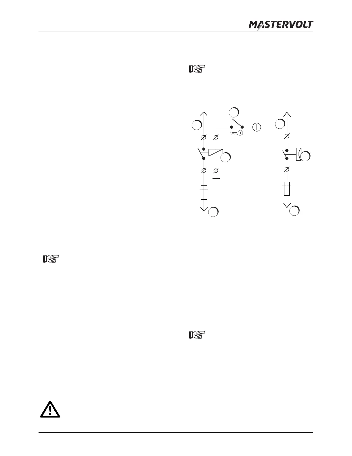
5
See reference . The brown cable of the cable
assembly must be connected to the [reg on]
terminal of the Alpha Pro II regulator. Connect
the other wire end through a switch (“S1”) with
normally open contacts to the positive (+) pole of
the battery as indicated. You can use the ignition
switch (figure 7) or preferably an independent
(ungrounded) oil pressure switch (figure 8). Use
a 2.5mm² cable. This cable must also be
secured by a 2 Amp fuse. As the [reg on]
terminal is also used for voltage measurement,
this cable should not be shared with other loads.
CAUTION!
If the engine is not running switch “S1”
must be open, otherwise the field
windings of the alternator will be
damaged due to overheating.
NOTE!
An additional toggle switch may be added
in series with switch “S1” to shut down
the alternator manually when increased
propulsion is needed.
Figure 7: Connection of the ignition switch (left) and
an independent (ungrounded) oil pressure switch
with normally open contact (right)
1. Brown wire
2. Ignition switch
3. Relay
4. Normally open oil pressure switch
5. Positive battery pole
6
See reference . The blue wire of the cable
assembly is the field connection of the
alternator. Connect this wire to the [field]
terminal of the Alpha Pro II regulator.
NOTE, only applicable for non-Mastervolt
alternators: With most other brands there
is an internal connection between the
negative field terminal of the alternator
(D–) and the alternator housing (GND).
Be sure to remove this connection before
installation. See APPENDIX section 2.5.
7
See reference . Attach the temperature sensor
to the battery and connect the RJ12 connecter to
the Alpha Pro II regulator as indicated.
reg on
reg on
2A
2A
S1
S1
1
1
3
5
4
5
2