INSTALLATION
14
January 2013/ Alpha alternator - Alpha Pro II regulator / EN
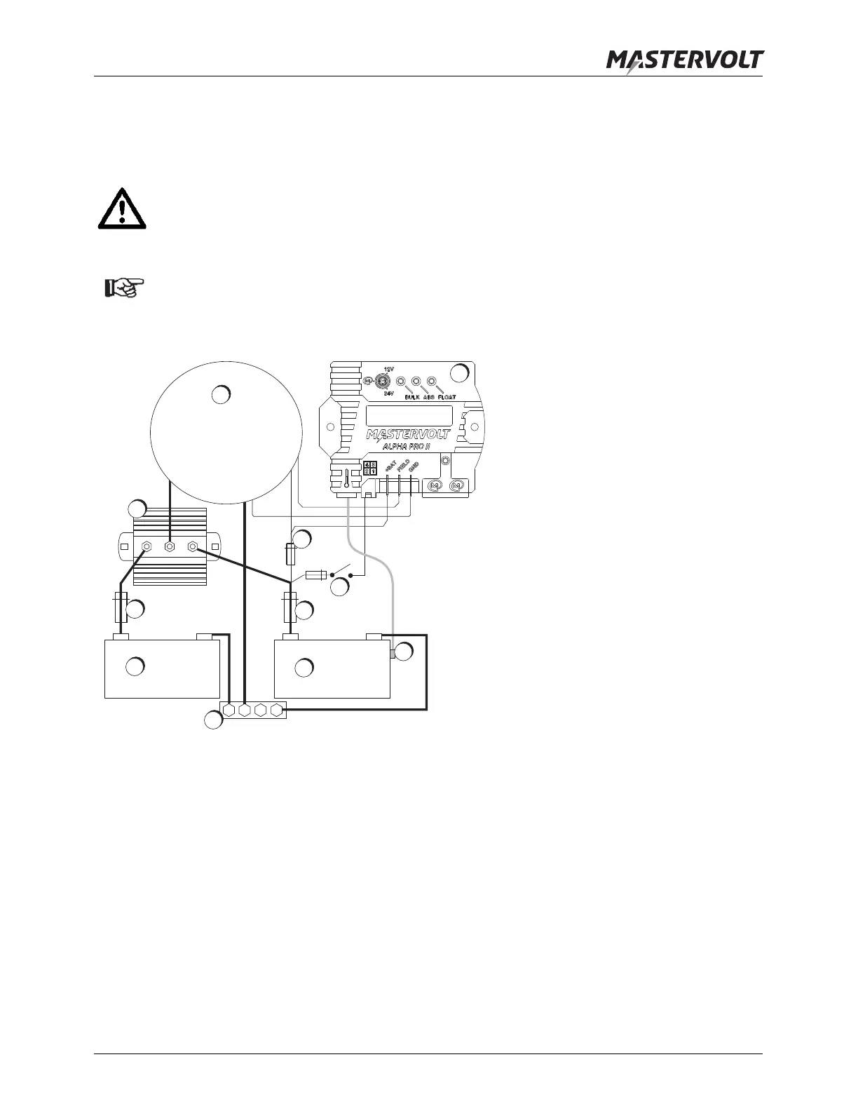
4.5.6 Use of a battery isolator (optional)
When two or more battery banks need to be charged simultaneously, using a battery isolator is recommended.
See figure 12 for installation details. See APPENDIX figures A-11, A-13 and A-14 for installation examples.
CAUTION!
If there is a battery isolator between the B+ terminal of the alternator and the positive (+) pole of the
battery, both the red [+bat] wire and the brown [reg on] lines must be connected to the positive (+) pole
of the battery. Do not connect these wires to the input of the battery isolator.
NOTE!
As battery voltage sensing is performed by the Alpha Pro II regulator, you can use a battery isolator
that has no voltage sense connection.
Figure 12: Installation of the Alpha Pro II
1. Alternator
2. Alpha Pro II regulator
3. Battery isolator
4. Auxiliary battery fuse
5. Auxiliary batteries
6. Main battery fuse
7. Main batteries
8. Minus bus bar
9. Battery sensor on main battery
10. 10A replaceable fuse between battery positive pole and alternator Field connector
11. Ignition relay or oil pressure switch, to be connected to Regulator On connection, number 1 in cable
assembly
+
_
+
_
10A
2A
B+
B-
Field
conn.
1
3
4
5
6
7
11
9
2
8
10