MASTERBUS
EN / Chargemaster1 12/35-3, 12/50-3, 24/20-3 & 24/30-3 / August 2009 17
6.2 HOW TO SET UP A MASTERBUS
NETWORK
Every device suitable for the MasterBus network is
equipped with two data ports. When two or more devices
are connected by these ports, they form a local data
network, called the MasterBus.
Keep the following rules in mind:
Figure 8
Figure 9
Figure 10
Figure 11
Figure 12
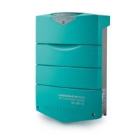
Connections between the devices are made by
standard straight UTP patch cables. Mastervolt can
supply these cables. These cables are also commonly
available at computer supply stores.
OK
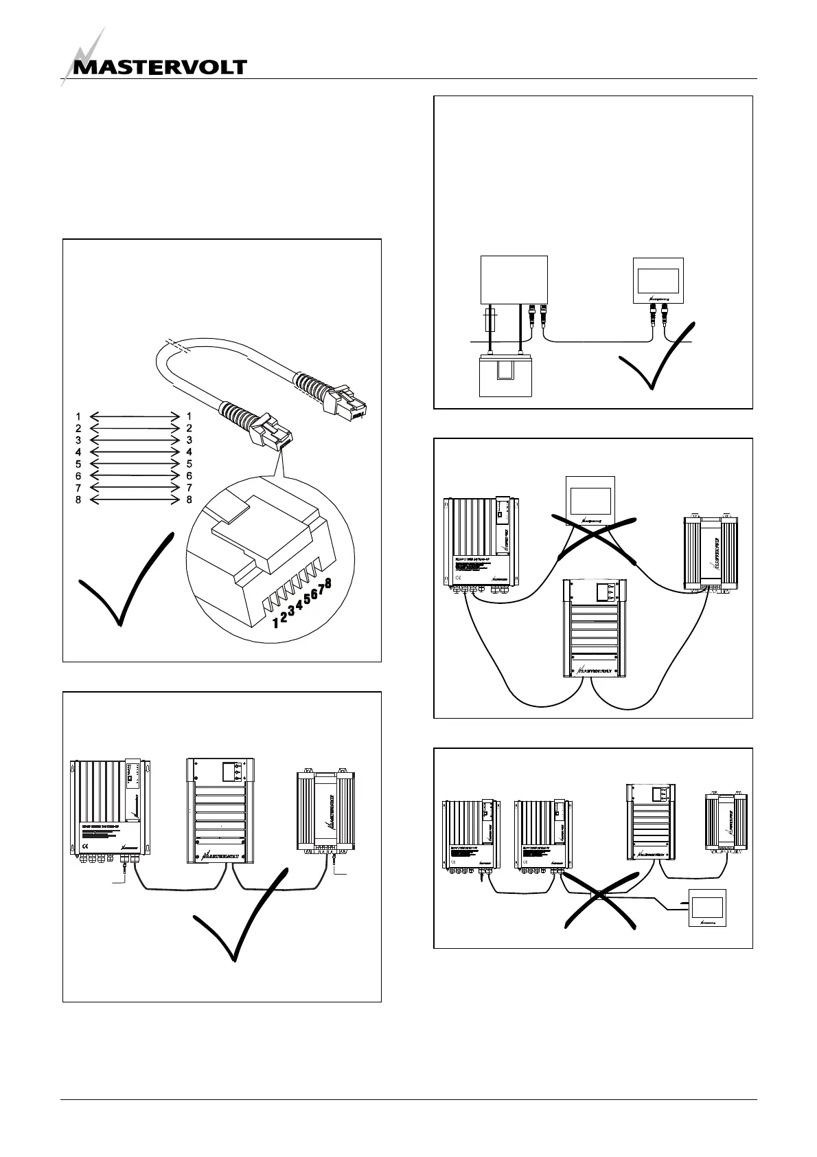
As with all high speed data networks, MasterBus
needs a terminating device on both ends of the
network.
Terminating
device
Terminating
device
OK
Do not make T-connections in the network.
Do not make ring networks
The connected devices provide the electric power for
the network. At least one device in the network should
have powering capabilities (see specifications).
One powering device can power up to three non-
powering devices. As all powering devices are
galvanically isolated, multiple powering devices are
allowed.
OK
 Loading...