CombiMaster 230V Series – User and Installation Manual
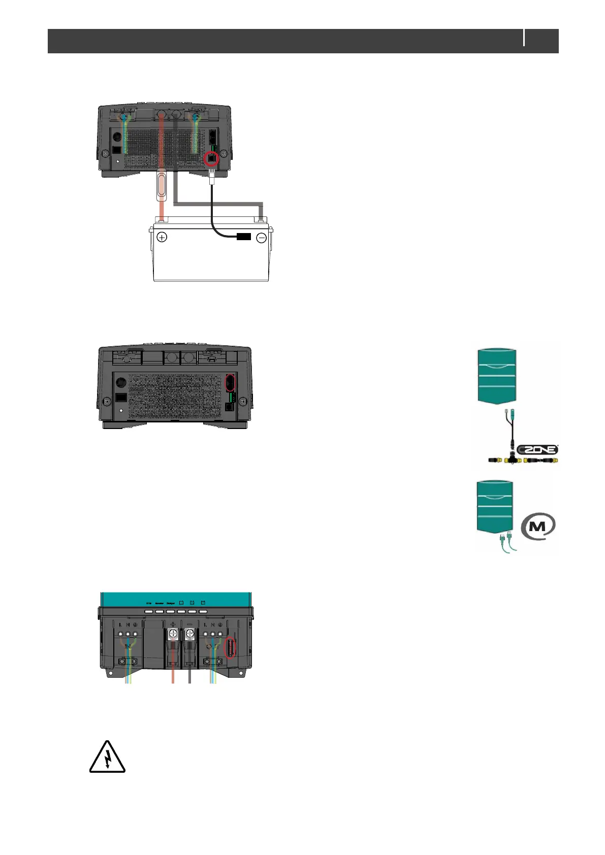
Step 9. Attach the battery temperature sensor to the casing of the battery bank. Then plug the temperature sensor cable
into the “temp.sensor” jack.
Note: Lithium-ion batteries require no temperature sensor.
Step 10. On the left side of the CombiMaster check the jumper selecting the grounding system.
See section 4.5.3 on page 10.
Step 11. Option: Connect the CombiMaster to the CZone or MasterBus network. See section 4.9 on page 15 for more
information on system integration.
Adding the CombiMaster to a CZone network
1 Disconnect the backbone at the closest
backbone connection and add in a tee
connector.
2 Reconnect the backbone connection(s) with
the new tee connector in place.
3 Connect the RJ45 CZone/MB drop cable to
the black coupler on the tee and then
connect to the CombiMaster.
Adding the CombiMaster to a MasterBus
network
1 Disconnect a MasterBus cable or Terminator
from the closest MasterBus device and
connect it to the CombiMaster.
2 Connect the new MasterBus cable to the
other MasterBus device and then connect to
the CombiMaster.
Ensure that the network is properly terminated.
Step 12. Option: use a small screw driver to change DIP switch settings. See section 5.1 on page 16.
Note: if added to a CZone network, the DIP switches are used to set the
CZone address during configuration.
Step 13. Option: connect external alarm or remote switch input. See section 4.8.
Step 14. Set the desired output voltage and other configuration settings using a remote control panel or the DIP switches.
See chapter 5.
Step 15. Check all wiring. If all wiring is OK: Place the inverter fuse.
WARNING!
When the fuse is placed, internal capacitors may cause a spark. This is normal
Step 16. Close the connection compartment and fix the screws at the bottom.
Step 17. Switch on the CombiMaster.