EasyManuals Logo

Mastervolt Mass Series User Manual

Mastervolt Mass Series
28 pages
To Next Page IconTo Next Page
To Previous Page IconTo Previous Page
Page #12 background imageLoading...
Page #12 background image
12
Mass 24/15-2, 24/25-2, 24/25-2 DNV, 24/25-2 (large cabinet) User and Installation Manual
4.13 Materials
Make sure you have all the parts you need to install the Mass Charger:
Product
Quantity
Mass Charger (included)
1
Battery temperature sensor with cable and plug (included).
1
DC-cable to connect the positive DC connection (+) of the Mass Charger to the positive pole of the DC-
distribution; for specifications see section 4.3.3.
1
DC-cable to connect the negative DC connection () of the Mass Charger to the negative pole of the DC-
distribution; for specifications see section 4.3.3.
1
DC-fuse holder with a DC-fuse, to be integrated in the positive DC-cable.
1
Screws / bolts (Ø 6mm) (with plugs) to mount the cabinet to a surface. Use mounting materials which are
suitable to carry the weight of the Mass Charger
4
AC cable* to connect the AC input to an external power source (e.g. a shore connection or a generator set);
1
Batteries. See section 4.4 for recommended capacity
X
Appropriate and reliable cable terminals, cable lugs, battery terminals and cord end terminals
X
* Double insulated three wire cable with wire colours according to the locally applicable regulations. The applicable length and
wire diameter depend on the electrical installation (see section 4.3.1).
We recommend as a minimum tool kit:
Socket wrench 13mm to fix the DC-input (battery) cables
Flat blade screwdriver 1.0 x 4.0 mm to fix the screw terminals
Tools to fix the screws / bolts (Ø 6mm) with plugs to mount the cabinets to a surface
Philips screwdriver to open the connection area of the Mass Charger
2 mm flat blade screwdriver for the sense terminal (figure 7 point 12).
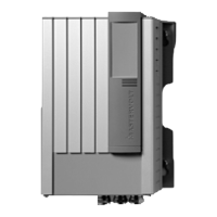
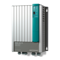
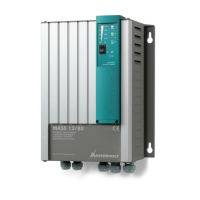
4.14 Connection
WARNING!
Let installation work be done by a licensed
electrician. Before beginning with the connection
of the wiring, make the AC distribution as well as
the DC distribution voltage free.
CAUTION!
Short circuiting or reversing polarity may lead to
serious damage to the batteries, the Mass
Charger, the cabling and/or the terminal
connections. Fuses between the batteries and
the Mass Charger can not prevent damage
caused by reversed polarity. The damage as a
result of reverse polarity is detectable by the
service department and is not covered by the
warranty.
CAUTION!
Too-thin cables and/or loose connections can
cause dangerous overheating of the cables
and/or terminals. Therefore, tighten all
connections well, to limit transition resistance as
far as possible. Use cables of the correct size.
Notes:
- If the battery temperature remains within 15-25°C,
connection of the battery temperature sensor is
optional.
- The Mass Charger is feasible for the connection of
MasterBus and RS 232 compatible remote control
panels.

Table of Contents

Questions and Answers:

Question and Answer IconNeed help?

Do you have a question about the Mastervolt Mass Series and is the answer not in the manual?

Mastervolt Mass Series Specifications

General IconGeneral
Output Voltage12V / 24V / 48V
CoolingFan or Natural convection (depending on model)
ProtectionOver temperature, Overload, Short circuit
DimensionsVaries depending on model
WeightVaries depending on model
Battery TypesGel, AGM, Lithium-ion
Temperature SensorYes
Parallel OperationYes
Input Voltage90-265V AC
Operating Temperature Range-20°C to +60°C

Related product manuals