6 MASTERBUS
6.1 What is MasterBus?
All devices that are suitable for MasterBus are
marked by the MasterBus symbol.
MasterBus is a fully decentralized data network for
communication between the different Mastervolt system
devices. It is CAN-bus based which has proven itself as a
reliable bus-system in automotive applications. MasterBus
is used as power management system for all connected
devices, such as the inverter, battery charger, generator
and many more. This enables communication between the
connected devices, for instance to start the generator when
the batteries are low.
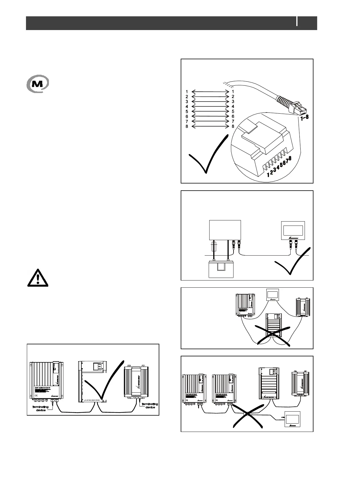
MasterBus reduces complexity of electrical systems by
using UTP patch cables. All system components are simply
chained together. Therefore, each device is equipped with
two MasterBus data ports. As only a few MasterBus cables
are needed, installation and material costs are reduced
importantly. New devices can be added to the existing
network easily. Consequently, the MasterBus network is
highly flexible for extended system configuration.
Mastervolt also offers several interfaces like the Modbus
and NMEA interface, making even non-MasterBus devices
suitable to operate in the MasterBus network.
For central monitoring and control of the connected devices
Mastervolt offers different remote control panels. All
monitoring panels can be used for monitoring, control and
configuration of all connected MasterBus equipment.
CAUTION!
Never connect a non-MasterBus device to the
MasterBus network directly! This will void
warranty of all MasterBus devices connected.
6.2 How to set up a MasterBus network
Every MasterBus device is equipped with two data ports.
When two or more devices are connected via these ports,
a local data network called the MasterBus is formed.
Keep the following rules in mind: