November 2004 / Masterlink MICC / EN 9
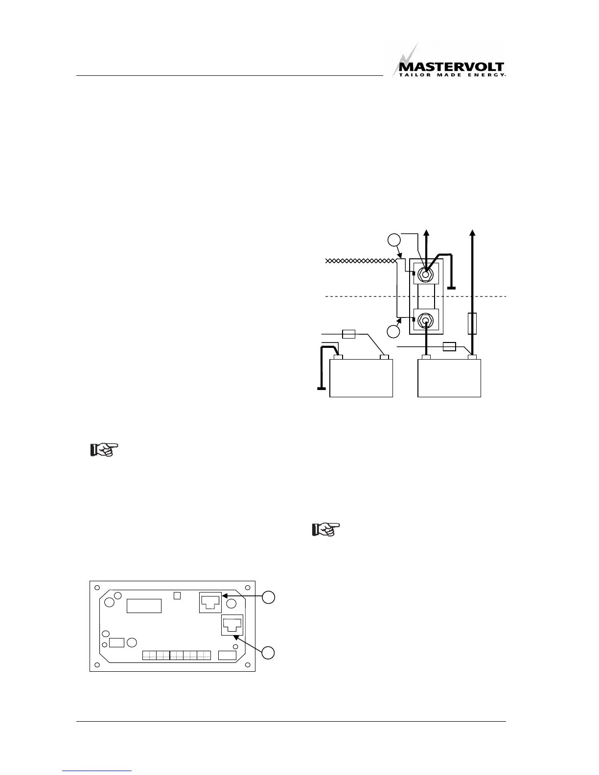
8. Run a 6 pole modular communication cable
(RJ12, cross wired) and connect the RJ12
connector to the socket on the right-hand
side (see figure 2: connector I) at the
backside of the Masterlink MICC.
To connect the other RJ12 connector to the
apparatus:
Refer to the charger’s installation
manual to connect the RJ12 connecter.
Mass Combi: You must connect the
RJ12 connecter to the “QRS-232” input
(Data bus connections) see figure 4.
9. Run another 6 pole modular communication
cable (RJ12, cross wired) and connect the
RJ12 connecter to the socket which is
marked with “Inv” (see figure 2: connector II)
at the back of the Masterlink MICC.
To connect the other RJ12 connector to the
apparatus:
Refer to the inverter’s installation
manual to connect the RJ12 connecter.
Option for the Mass Combi: Connect
the RJ12 connecter to the “REMOTE”
input (Data bus connections) see fig. 4.
NOTE: under normal circumstances
there is no need to install this
optional cable. If this cable is installed, the
total stand-by power consumption will be
reduced from 50mA to 30mA if the Mass
Combi is switched off by means of the
Inverter button on the Masterlink MICC
panel.
When installed, it is not possible to connect
the ICC remote control panel to the Mass
Combi.
Figure 2: Backside MICC panel
10. Connect the wires to the connection
terminals of the Masterlink MICC and mount
the panel with the four factory supplied nuts
and rings.
11. Connect the minus wire of the system to the
system side (see figure 3) of the shunt.
12. Make a connection between the minus of the
secondary (starter) battery and the system
side (figure 3) of the shunt.
13. Connect the battery side of the shunt (figure
3) to the minus terminal of the main battery.
NOTE: if several minus cables are
connected to the minus terminal of the
main battery, all of these cables must
be connected to the system side of the
shunt. On the battery side only one
cable between shunt and main battery
is used.
14. Reconnect the positive terminals of the
batteries to the system.
15. Double check the wire connection of the
meter and install the three 2 amp fuses.
– +
Secondary
battery
– +
Main battery
È Battery side
3
4
Ç System side
Charger
Inverter
Load
Figure 3
I
II