10 November 2004 / Masterlink MICC / EN
Directly after power up by installing the two
2 amp fuses the LED.'s will light and after
approximately five seconds the display will
show the volt, amps, state of charge and the
time remaining of the main battery.
If this is not the case, check the wire
connections for errors. Consult to the trouble
shooting chapter if the wires are connected
correctly but the meter is not showing the
display (chapter 13).
3.4 Installation of an external alarm
The switching current of the alarm relay
(normally open contact) may never exceed
1A@30VDC. The switching contacts of the relay
are available on pin 9 and 10.
3.5 Connection of the charger and the
inverter
Always connect the cables between batteries
and charger and inverter, before you connect
the Masterlink MICC to the charger or inverter.
If it is necessary to disconnect batteries and
charger/inverter, then first disconnect Masterlink
MICC from the charger/inverter
For an appropriate operation of the Masterlink
MICC the “ON/OFF” switch of the inverter must
be set to the “REMOTE” position.
If you are using a Mass Combi then the
ON/OFF/CH. switch on the front of the Mass
Combi must be set in the “ON” or “Ch. Position.
See chapter 4 of the manual of the Mass
Combi.
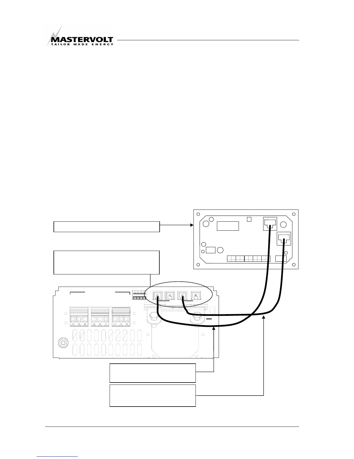
Step 9: optional 6 pole modular
cable RJ12, cross wired
Step 8: 6 pole modular cable
RJ12, cross wired
Connection compartment of the Mass
Combi. See chapter 5 of the manual of
the Mass Combi.
Rear view of the Masterlink MIC