INSTALLATION
EN / MasterShunt / February 2011 11
5.2.1 DC wiring installation
NOTE:
Remember to put the cones around the
cables before connecting!
Step 1 Position the MasterShunt between the
battery and the load/ charger.
Connect the loose positive battery cable to the upper
left connection(A) and the positive load cable to the
upper right connection(B).
Step 2 Connect the negative battery cable to D and
the negative load cable to C.
Use cable lugs to accomplish sufficient electrical
contact between the wiring and the MasterShunt.
The recommended tightening torque is 15-20 Nm.
NOTE:
The charger must be connected at the load
side of the MasterShunt!
CAREFUL!
Leave the positive battery cable
disconnected from the battery.
5.2.2 MasterBus wiring installation
Connect two or more MasterBus devices with
MasterBus cable. Put a MasterBus terminator at
both ends of the network. Refer to section 4.2 for
further details on how to set up a MasterBus
network.
NOTE:
Always place a terminator at both ends of
the MasterBus network.
5.3 COMMISSIONING
Check if all wiring is OK. Then:
• (Re)connect the positive battery cable.
• Proceed with chapter 6, “FIRST START UP”
Figure 10: Commissioning
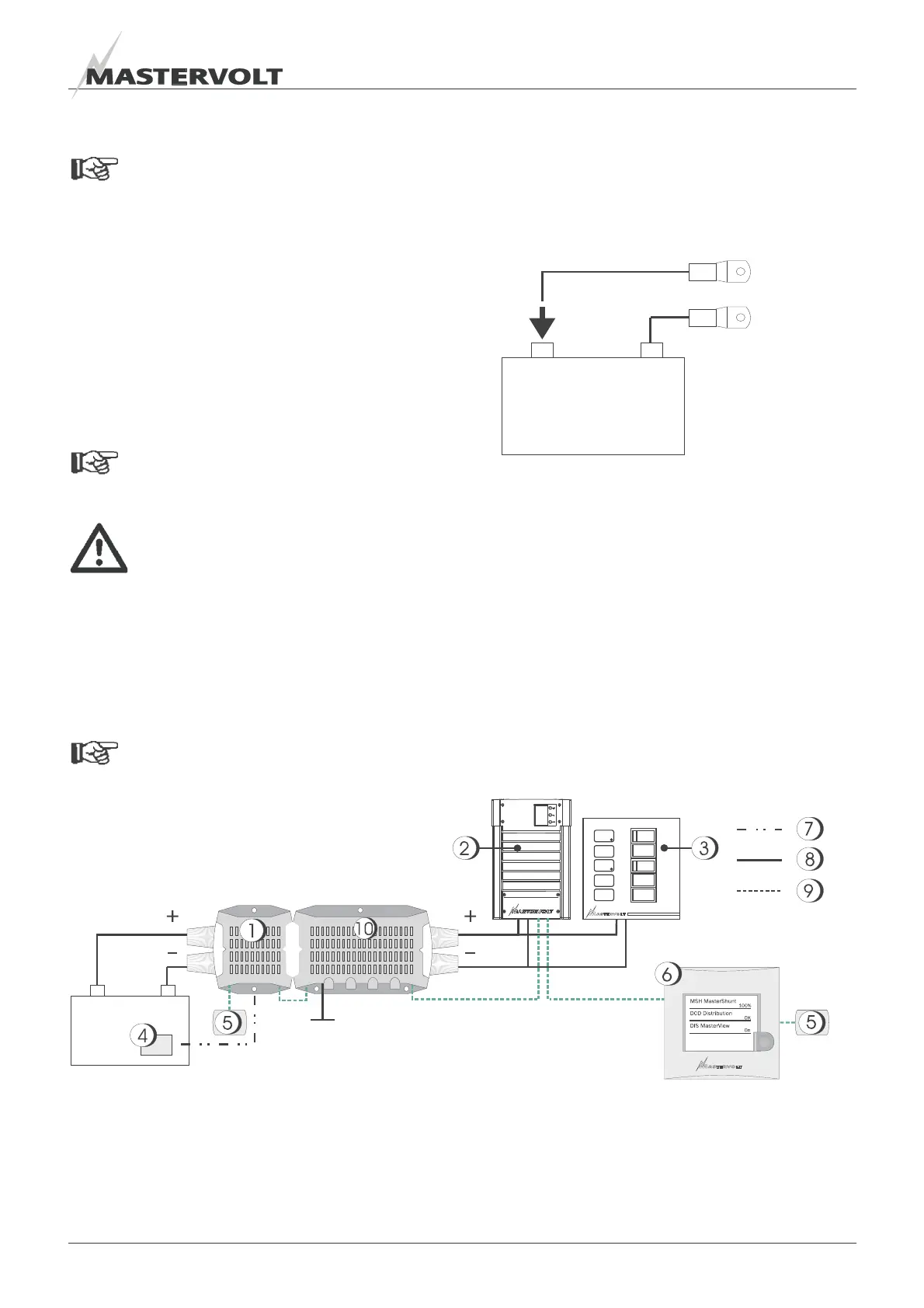
5.4 SYSTEM EXAMPLES
Figure 11 shows an example of the MasterShunt in
combination with a charger and a distribution panel.
Note the position of the charger at the load side and
the MasterBus cables between the MasterBus
devices.
Figure 11: System example 1
1 MasterShunt
2 Charger
3 Switchboard
4 Temperature sensor on battery
5 Terminator for MasterBus
6 MasterView Easy display
7 Temperature sensor wiring
8 DC wiring
9 MasterBus wiring
10. DC Distribution 500,
connected via MasterConnect
+
_
+
_