TROUBLE SHOOTING
38 Copyright © 2008 Mastervolt / December 2008 / Whisper 12 Ultra - Three phase for mobile applications/ EN
5.4 SPECIAL PROCEDURES ENGINE
5.4.1 Setting the RPM
RPM is set by the manufacturer and should not need
readjustment! When adjustments are necessary this can
only be done with the help of an interface to a computer
and special software to get access to the microprocessor.
If readjustment of the RPM is necessary, please contact
your Mastervolt Service Centre for advice:
5.4.2 Adjusting valve clearance and
retightening the cylinder head bolts.
Both procedures have to be carried out with a cold engine.
When both procedures are carried out be sure to retighten
the cylinder head bolts before adjusting the valve
clearance. When retightening the cylinder head bolts,
drain the coolant by removing the drain plug (ref. to fig. 4 –
7).
Loosen the bolts slightly, remove the rocker assembly (the
rocker arms, shaft, and stays) and then retighten the bolts
to the specified torque in the numerical order illustrated
(ref. to fig. 28).
Tightening torque cylinder head bolt: 88 ± 5 Nm
Rocker stay tightening torque: 14.7 ± 2 Nm
Fig 28 Cylinder head bolts
The clearance of both (intake and exhaust) valves should
be 0.25 mm in cold condition. Set the piston of the first
cylinder to be adjusted to top dead centre (T.D.C.) of
compression stroke.
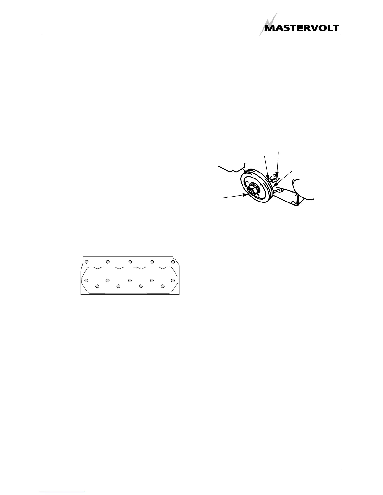
The T.D.C. of compression stroke can be found by
aligning the T.D.C. mark (notch) on the crankshaft pulley
with the mark on the gear case (ref. to fig. 29).
First align the T.D.C. mark for the No. 1 cylinder. Confirm
that the valves do not move up or down when the
crankshaft is turned about 20 degrees in normal and
reverse direction of rotation.
Figure 29
If the rocker arms move piston no.1 is on the T.D.C. of the
intake or exhaust stroke. In such case turn the crankshaft
360° in the direction of engine rotation again. No. 1 piston
is now at T.D.C. of the compression stroke.
After adjusting the valves of cylinder 1 adjust the valve
clearance of the remaining cylinders in firing order 1 – 3 –
4 – 2. Turn the crankshaft 180 degrees clockwise from the
T.D.C of cylinder 1 to the T.D.C of cylinder 3. and turn the
crackshaft 180 degrees further clockwise to the TDC of
cylinder 4 and adjust the valves. And again 180 degrees to
adjust cylinder 2.
10 4 2 5
7
861 39
14 12 1 13
1
FRONT
MOTOR
Mark on timing gearcase
IT (injection timing)
mark
TDC mark piston 1 and 4
TDC mark piston
2 and 3

 Loading...


