INSTALLATION
EN / WHISPER 3.5 / October 2009 / Copyright © 2009 Mastervolt 7
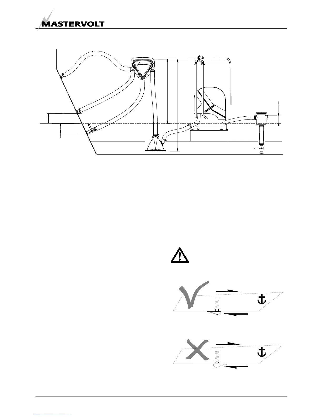
Figure 5: Internal cooling system
1.4.2 Cooling
Intercooling is based on a raw water pump, heat
exchanger and water-injected exhaust.
The generating set should have its own sea water (coolant
water) inlet and should not be connected to any other
engine systems. A properly installed cooling system is
critical to keep engine temperatures within an acceptable
range. Ensure that the installation complies with the
following installation instructions.
1 RAW WATER SUPPLY
For raw water supply the following installation materials
are required: -a skin fitting - a sea cock - a water strainer -
hoses and clamps. In order to keep the suction resistance
in the line at a minimum, the sea water intake system (i.e.
sea cock, tru-hull fitting, inlet filter, etc.) must have an
inner diameter of at least 12.5 mm diameter (1/2"). The
suction hose should be kept as short as possible. Raw
water plumbing should avoid bends as much as possible.
Restriction of raw water flow, caused by kinked hoses,
undersized pipes or connections, will reduce the engine
cooling capability. This is the main cause for overheating
of an engine.
After running the generating set for the first time, check the
coolant flow rate using a stopwatch and by holding a pail
of a known volume under the wet-exhaust outlet. The flow
rate should be 8 to 12 litres /min.
2 INSTALLATION OF THROUGH HULL FITTING
It is good practice for yachts to use a hull inlet fitting with
an integrated strainer (water scoop). For propulsion
engines in motorboats the water scoop is often mounted
against the sailing direction to induce more water intake
for cooling.
This should not be done in the case of a
generating set! When sailing at higher
speeds, water will be forced into the inlet and
your generating set will overflow!
Figure 6 Installing water intake
MIN. 60CM (24")
MAX. 150CM (60")
5
6
2
MAX. 10CM (4")
MIN. 3CM (1,2")
3
1
4
7
5CM (2")
1 Water level 5 Air vent;
2 Water/exhaust separator 6 Water strainer;
3 Seacock 7 Seacock.
4 Waterlock
SAILING DIRECTION
SAILING DIRECTION
FLOW DIRECTION
FLOW DIRECTION