TROUBLE SHOOTING
EN / Whisper 6 Ultra for mobile applications / December 2009 / Copyright © 2009 Mastervolt 33
5.3 SPECIAL PROCEDURES ALTERNATOR
5.3.1 Residual voltage check / excitation
procedure
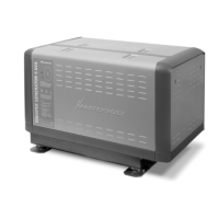
When residual magnetism disappears there is no residual
voltage. Residual magnetism can disappear after the
generating set being out of service for a long period or a
short circuit. This can be solved by charging the capacitor
("flashing") independently with a small 9 Volt battery. This
can be done while the engine is stationary and the wiring
is connected.
If the generating set battery is used for
flashing one must take care. A short circuit
can cause heavy sparking, fire and injuries
When flashing does not bring back voltage, the
capacitor(s) should be renewed. When this does not help,
the rotating rectifier diodes should be tested and a winding
resistant test should be executed.
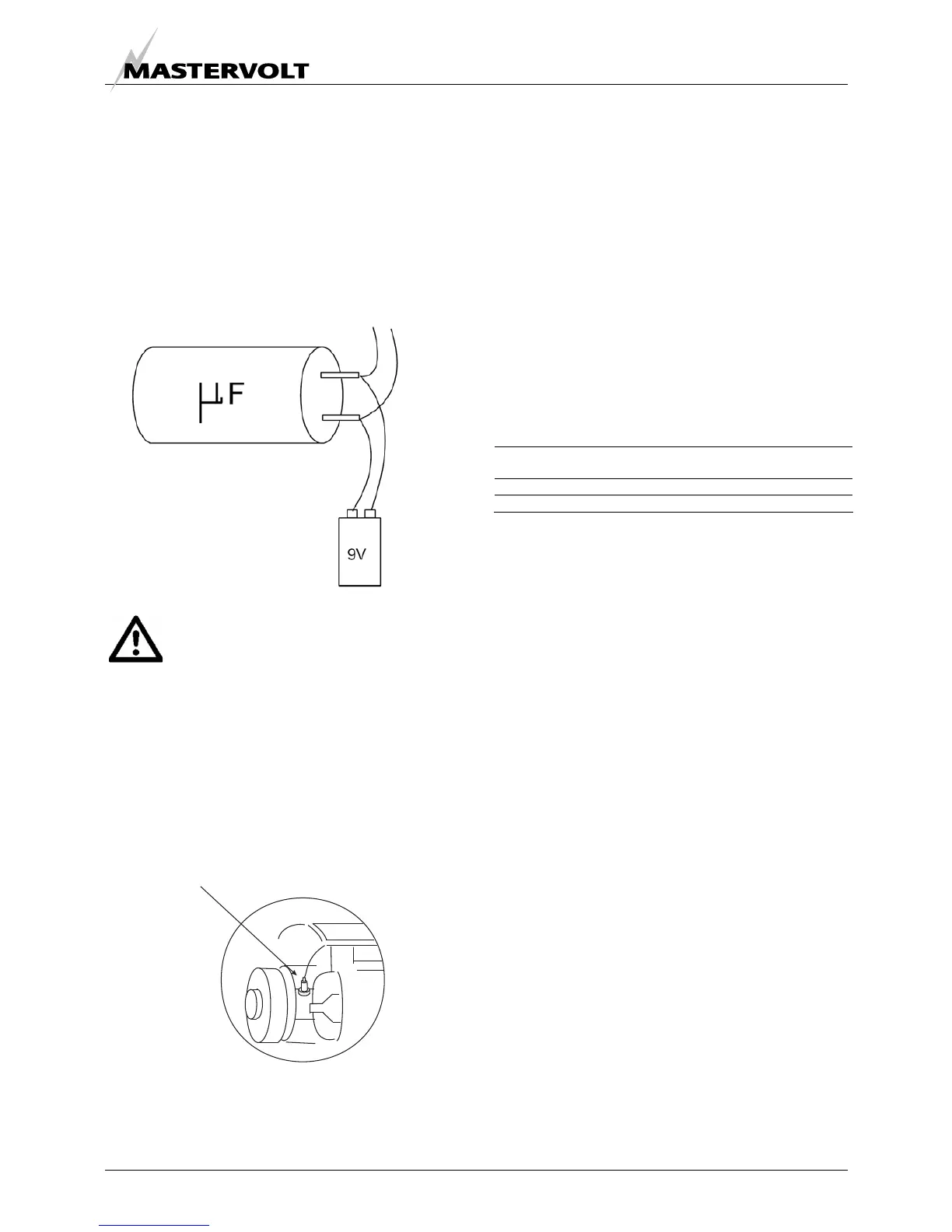
5.3.2 Testing rotary rectifier diodes
The diodes in the rotor can be checked with a multimeter.
When the diode is faulty the alternator will not generate
any voltage.
The flexible lead connected to the diode should be
disconnected at the terminal end, and the forward and
reverse resistance checked. A healthy diode will indicate a
very high resistance (infinity) in the reverse direction, and
a low resistance in the forward direction. A faulty diode will
give a full deflection reading in both directions with the test
meter on the 10,000 ohms scale, or an infinity reading in
both directions. Replace the diode.
5.3.3 Winding resistant values
If after establishing and correcting any fault on the
capacitor and diode output is still low when separately
excited, then the main rotor, stator and exciter stator
winding resistance should be checked as the fault must be
in one of these windings. The respective leads must be
disconnected before taking the readings.
Resistance values should be within 10% of the values
given in the table below:
Whisper 6 ULTRA
Resistance 50Hz-230v
x Resistance both main stator windings
in series
0.77 Ohm
x Resistance both rotor windings
2.0 Ohm
x Resistance exciter stator winding
1.91 Ohm
5.3.4 Meggering
One can try to measure resistance between the housing
and the windings with a multimeter which should read
infinity. When readings are infinity but a fault is suspected
one can do a high voltage resistance test (MEGGERING)
This procedure should be carried out by an expert
Fig. 25.
Fig. 26
DIODE
 Loading...


