17
Section 8: Wireless
Section 8:
Wireless
Transceiver Setup
Receiverver Setup
1. Set the upper 5 DIP switches on the transceiver to the same baud
rate as the indicator. If all switches are set to off or more than one
switch is turned on then the unit will default to 9600 baud
2. Set the dip switch 1 to 4 on the transceiver for a system ID. There
are 16 possible system IDs available 0 (all off ) to 15 (all on). If more
than one wireless system are present each system requires a unique
ID
3. Press the CONFIG button on the transceiver to save the dip
switch settings. The three green configuration LEDs will illuminate as
setup progresses. LED 1 indicates setup initiated. LEDs 1 and 2
indicate internal communication established. LEDs 1, 2, and 3
indicate setup complete. If there is a problem with configuration the
red CONFIG LED will blink every 5 seconds up to 6 times as internal
communication is re-established. The red CONFIG LED will then
blink several times rapidly. Wait a minimum of 5 seconds before
pressing CONFIG again.
4. Wire the transceiver to the indicator according to Figure 1. When
properly wired the corresponding LED (RS232, CLOOP, or RS422)
will blink with each data transmission
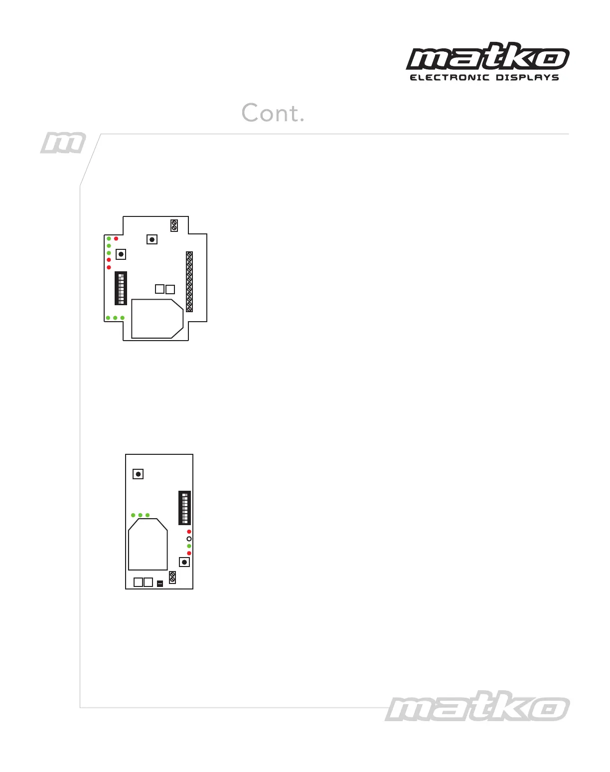
Figure 2 - XT300
Transceiver
+9 V DC
GND
232 RXD
232 TXD
CL(-)
CL(+)
RX 422A
RX 422B
T X CL(-)
T X CL(+)
T X 422A
T X 422B
U8
U5
PWR
RS232
CLOOP
RS422
TX
CONFIG
1 2 3
CO NF I G
1200
2400
4800
9600
19200
ID +1
ID +2
ID +4
ID +8
CONFIG
STEPS
RE SE T
+GND
+9
1. Set the dip switch 5 to 9 on the transceiver to the same baud rate
as the indicator. If all switches are set to off or more than one switch
is turned on then the unit will operate at 9600 baud.
2. Set the dip switch 1 to 4 on the transceiver for a system ID. There
are 16 possible system IDs available, 0 (all off ) to 15 (all on) for the
XT300, 2 IDs for the XT200 and 1 ID for the XT100. If more than one
wireless system is present each system requires a unique ID. All
transmitters and receivers on the same system must have the same
system ID
3. Press the CONFIG button on the transceiver to save the dip switch
settings. The three green configuration LEDs will illuminate as setup
progresses. LED 1 indicates setup initiated. LEDs 1 and 2 indicate
internal communication established. LEDs 1, 2, and 3 indicate setup
complete. If there is a problem with configuration the red CONFIG
LED will blink every 5 seconds up to 6 times as internal
communication is re-established. The red CONFIG LED will then blink
several times rapidly. Wait a minimum of 5 seconds before pressing
CONFIG again.
4. The RX LED will blink to indicate that the scoreboard is receiving
the wireless signal.
1 2 3
CONFIG STEPS
PWR
TX
RX
CONFIG
CONFIG
1200
2400
4800
9600
19200
ID +1
ID +2
ID +4
ID +8
RESET
IO 0
IO 1
U13
U9
IN
OU T
IN
OUT
Figure 3 - XT300
Receiver