43
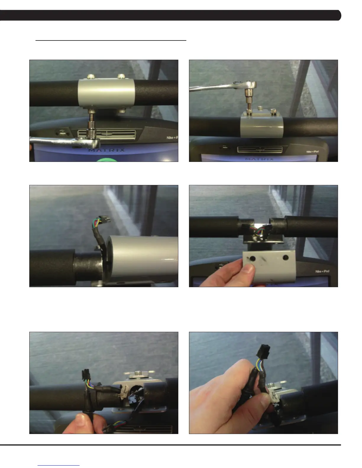
- Remove the 2 screws going into the handlebar connection frame from the bottom (Figure E).
- Remove the 3 screws going into the handlebar connection frame from the top (Figure F).
- Pull the handlebars out of the handlebar connection frame, and disconnect the grip wiring on each side (Figure G).
- Remove the handlebar connection frame from the unit (Figure H).
- Perform a continuity test on the wiring going from the toggle to the handlebar connection frame. With a multi-meter set for ohms, place
one prong on the toggle wiring coming out of the handlebar (Figure I) and one prong on the wire on the toggle connector (the toggle wires are
yellow, blue, and green - match similar colors). An ohm reading of less than 1 should be expected. If this reading is higher than 1, or if there is
not a reading, replace this section of the grip wiring.
- Repeat the previous step with the opposite side grip wiring (Figure J).
FIGURE FFIGURE E
FIGURE JFIGURE I
FIGURE HFIGURE G
8.16 TROUBLESHOOTING - TOGGLE ISSUES - CONTINUED
CHAPTER 8: TROUBLESHOOTING