30
Chapter 2: Powering and connecting to your Matrox Iris GTX
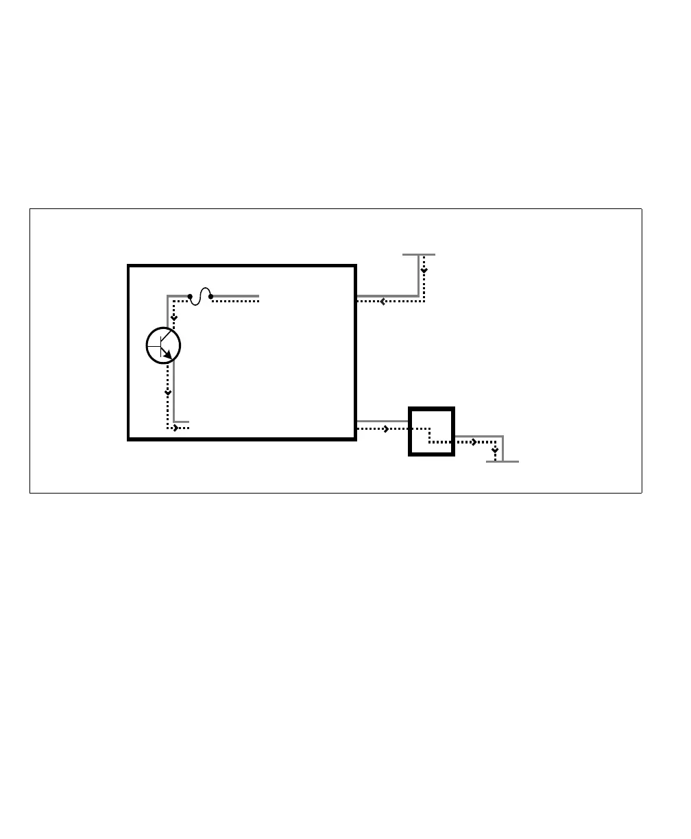
You can also connect a single auxiliary output signal in a sourcing configuration,
such that the common pin is connected to a sinking device and the dedicated pin
is connected to the power supply. However, in this configuration, the other two
auxiliary output signals are not available. The exact connection between the output
signal, the connected device, and the power source depends entirely on the type
of device to which you connect.
When an auxiliary output signal is on, the circuit between its AUX_OUT pin and
AUX_OUT_COMMON pin is closed, allowing current to flow from the
AUX_OUT pin to the AUX_OUT_COMMON pin, if the AUX_OUT pin is
attached to a power source or a sourcing device. When an auxiliary output signal
is off, the circuit between the AUX_OUT and AUX_OUT_COMMON pins of
the signal is open and no current flows through.
Important
Note that the power source must be provided externally.
Equivalent circuit only
Connecting one sourcing auxiliary output signal to a sinking device.
Matrox Iris GTX
(in a sourcing configuration)
AUX OUT_ _COMMON
Up to 24 V
Sinking device
+
-
fuse
VDC- (typical)
AUX OUT_0