Connecting to the auxiliary I/O interface 29
Connecting devices to the auxiliary output signals
Matrox Iris GTX auxiliary output signals can be interfaced with input modules
(with sourcing or sinking input signals) found on most programmable logic
controllers (PLCs) and other devices. The auxiliary output signals can also be
interfaced with inductive load devices (such as a relay or a small motor).
The Matrox Iris GTX auxiliary output signals are sinking output signals, based
on an NPN-type transistor. They need to be connected to an external power source
because on their own, they are not capable of providing voltage to drive a device.
They are typically connected in a sinking configuration because they only have
one dedicated pin (AUX_OUT0, AUX_OUT1, AUX_OUT2, respectively) and
share their other pin (AUX_OUT_COMMON). So, typically, a sourcing device
is connected to their dedicated pin and the return path is connected to the
common pin. The exact connection between the output signal, the connected
device, and the power source depends on the type of device to which you connect.
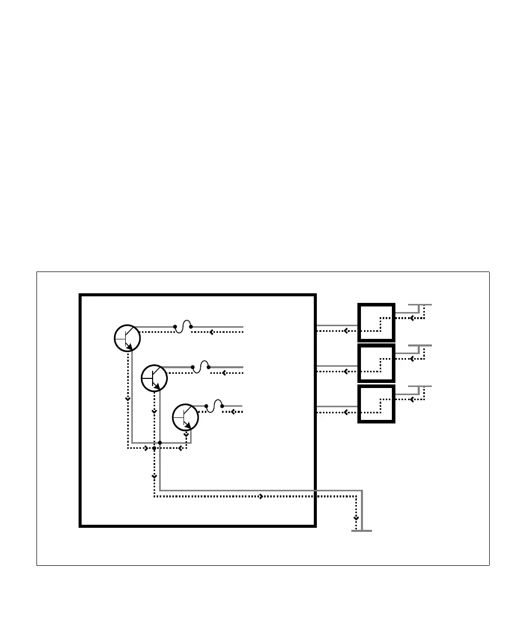
Equivalent circuit only
Matrox Iris GTX
(in a sinking configuration)
AUX OUT_1
AUX OUT_ _COMMON
AUX OUT_0
AUX OUT_2
VDC- (typical)
Sourcing devices
Connecting three sourcing devices to sinking auxiliary output signals
fuse
fuse
fuse
-
+
Up to 24 V
-
+
Up to 24 V
-
+
Up to 24 V